Stepping switch mechanism

A step switch and switch technology, applied in the direction of non-polar relays, relays, electrical components, etc., can solve problems such as complex structures, and achieve the effect of ensuring the function of preventing reversal

Inactive Publication Date: 2004-10-20
SIEMENS AG
View PDF1 Cites 5 Cited by
  • Summary
  • Abstract
  • Description
  • Claims
  • Application Information

AI Technical Summary

Problems solved by technology

Therefore, the structure of the step switch mechanism is more complicated

Method used


Image

  • Stepping switch mechanism
  • Stepping switch mechanism
  • Stepping switch mechanism

Examples


Embodiment Construction

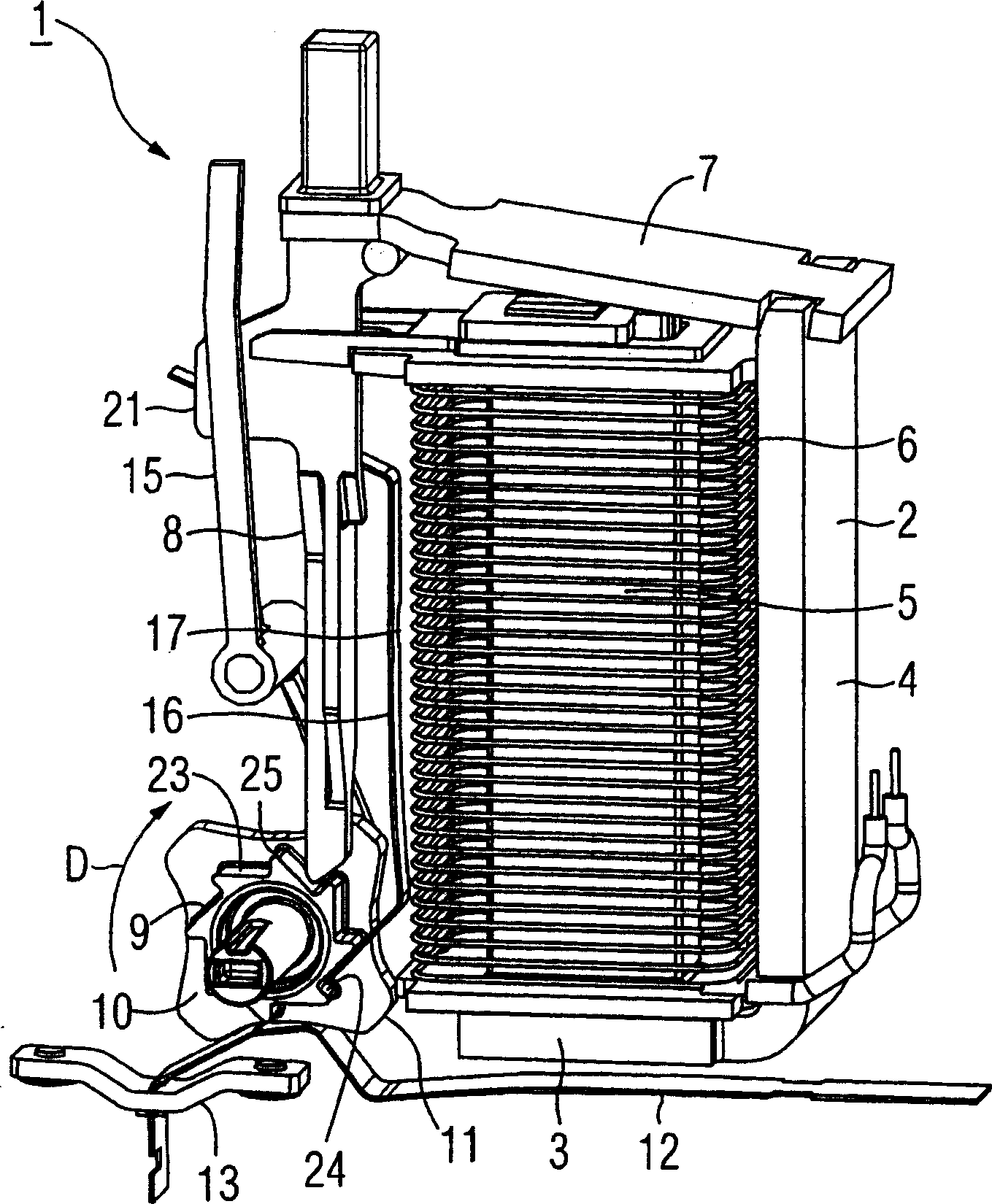
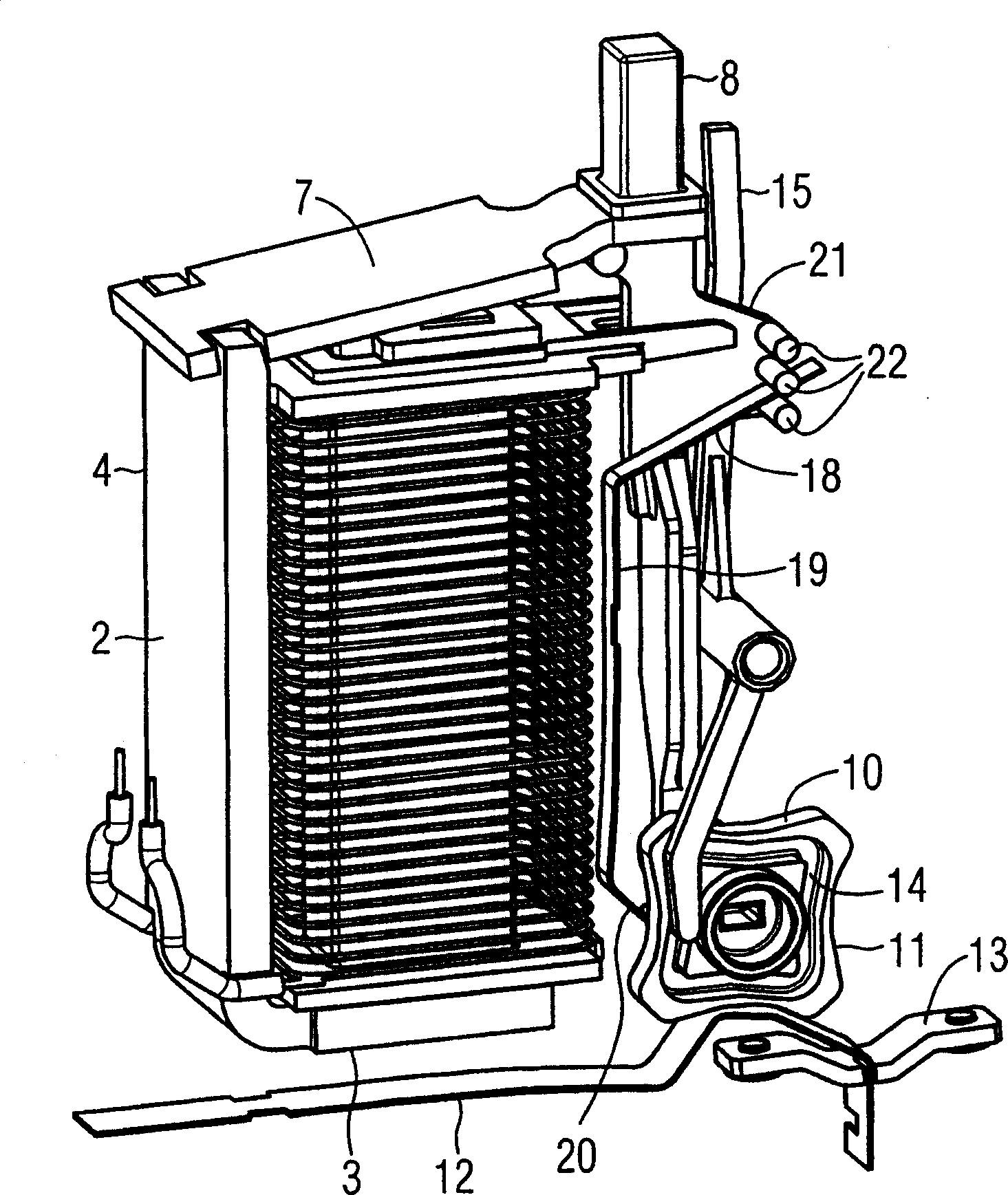
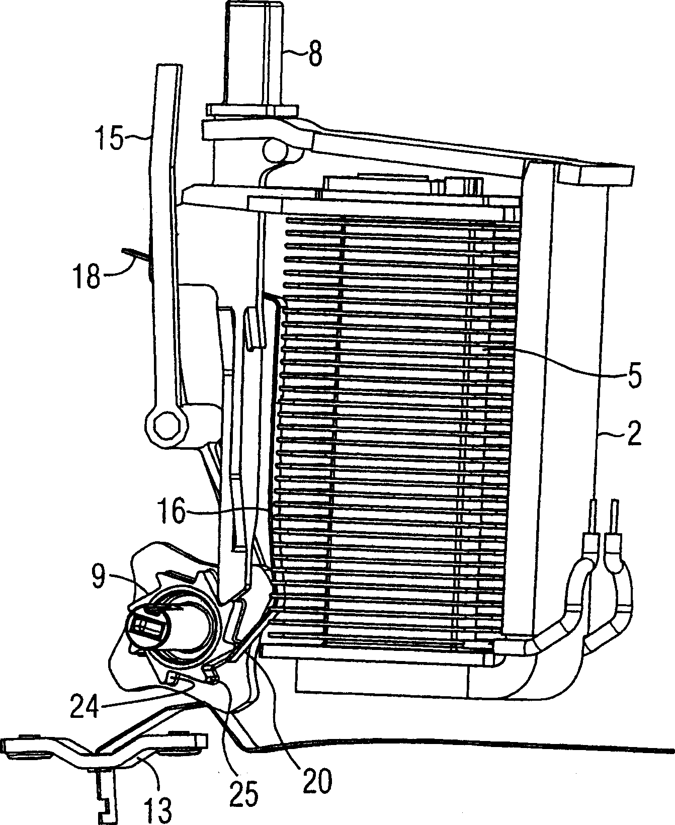
[0031] figure 1 and figure 2 A step switching mechanism 1 in a step relay for remote control of a current circuit, not further shown here, is shown. The step switch mechanism 1 has an L-shaped yoke 2 with a first short arm 3 and a second long arm 4 . Arranged parallel to the second long arm 4 on the first short arm 3 is an iron core 5 surrounded by a coil 6 . On the end side of the second long arm 4 a pivot armature 7 is movably connected thereto. On the end of the pivot armature 7 remote from the second long arm 4 , a switch push rod 8 is connected to it, wherein the push rod 8 is at least slightly pivotable relative to the pivot armature 7 . The switch push rod 8 runs essentially parallel to the core 5 and the coil 6 as well as the second long arm 4 . The switch push rod 8 cooperates directly with the ring gear 9 on a ratchet 10 . The number of teeth of the ring gear 9 here is 8, corresponding to the eight determined switch positions of the ratchet 10 , each separated ...


PUM


Abstract

The stepping switch mechanism has a magnetic system with a magnetic coil (6) and a pivoted armature (7), cooperating with a switch rod (8), in turn cooperating with a switch wheel (10) which is moved between a number of defined switch positions. A spring element (16) has 3 spring arms, respectively acting on the switch rod, secured to the housing of the switch mechanism and cooperating with the switch wheel.

Description

technical field [0001] The invention relates to a stepping switch mechanism placed in an electromagnetic stepping relay with a housing, comprising a magnetic system with a coil and a pivot armature, a magnetic system preferably cooperating directly with the pivot armature The switch push rod and a ratchet that works together with the switch push rod and can be locked in several determined switch positions. Background technique [0002] Such a step switch mechanism is known, for example, from German patent specification DE 35 19 546 C2. [0003] Stepping switch mechanisms are commonly used in current pulse switches, where a ratchet operating multiple contacts can be locked in certain switch positions and can only be turned in one direction. In order to realize the required switching function, the stepping switch mechanism therefore has a plurality of movable, in particular elastic, functional parts. Therefore, the structure of the step switch mechanism is relatively complic...

Claims


Application Information

Patent Timeline
Patent Type & Authority Applications(China)
IPC IPC(8): H01H51/08
CPCH01H51/086
Inventor 理查德·戈特勒
Owner SIEMENS AG
Why Eureka
Try Eureka