

Lineprinter and its controlling method
A control method and printer technology, applied to printing devices, printing, etc., can solve problems such as DC motor detection errors and increased deviations
Inactive Publication Date: 2004-11-03
SEIKO EPSON CORP
View PDF1 Cites 4 Cited by
- Summary
- Abstract
- Description
- Claims
- Application Information
AI Technical Summary
Problems solved by technology
Therefore, due to the detection error of the rotation of the DC motor, there is a danger that the above-mentioned variation in the line interval will further increase.
Method used
View moreImage
Smart ImageViewing Examples

Examples
other Embodiment approach
[0075] In the above-mentioned embodiment, the method of applying the present invention to a thermal printer has been described, but the present invention is not limited to thermal printers, and can be applied to all types of inkjet printers, impact printers, etc. line matrix printer.
Login to View More PUM
 Abstract
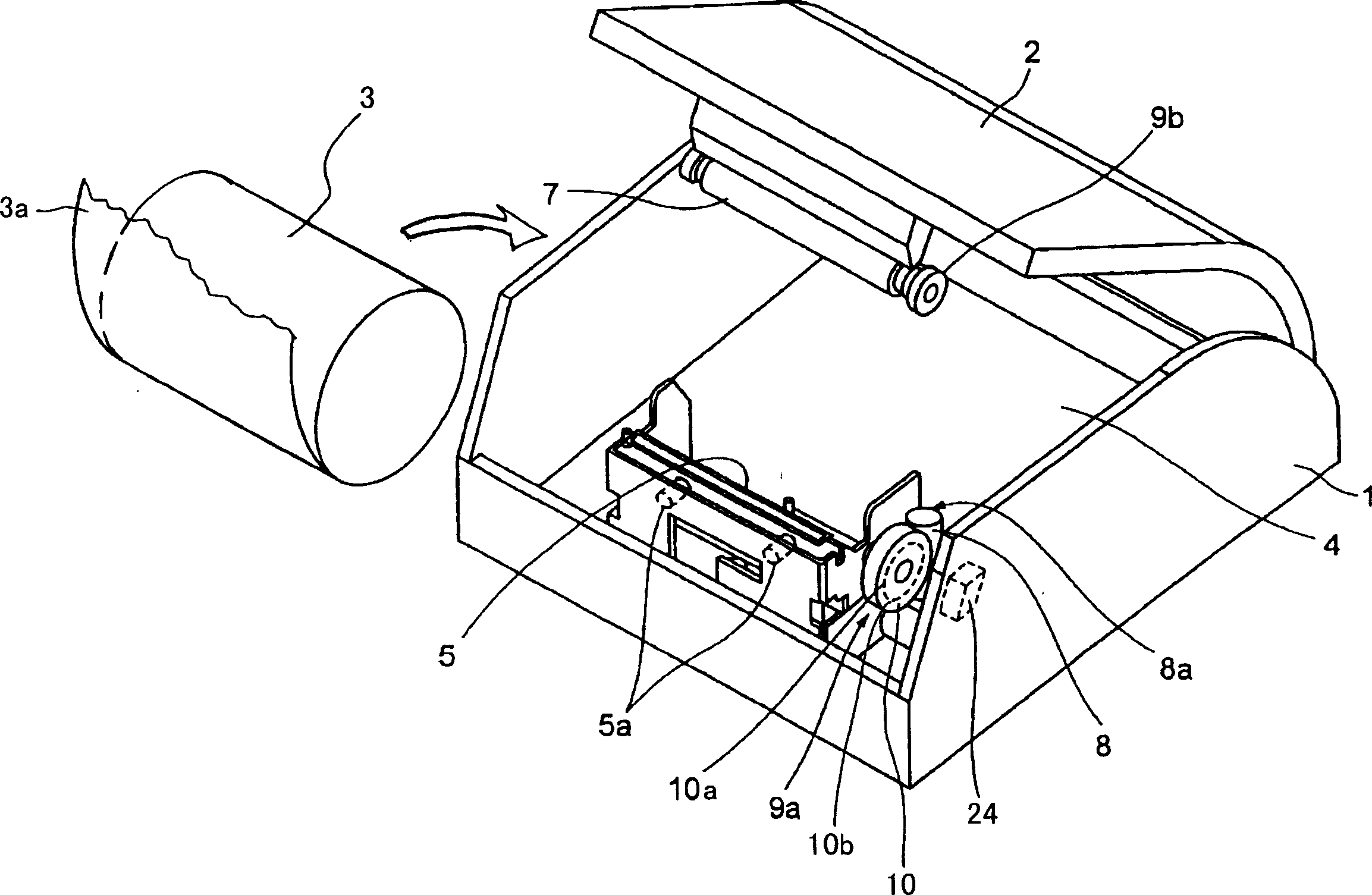
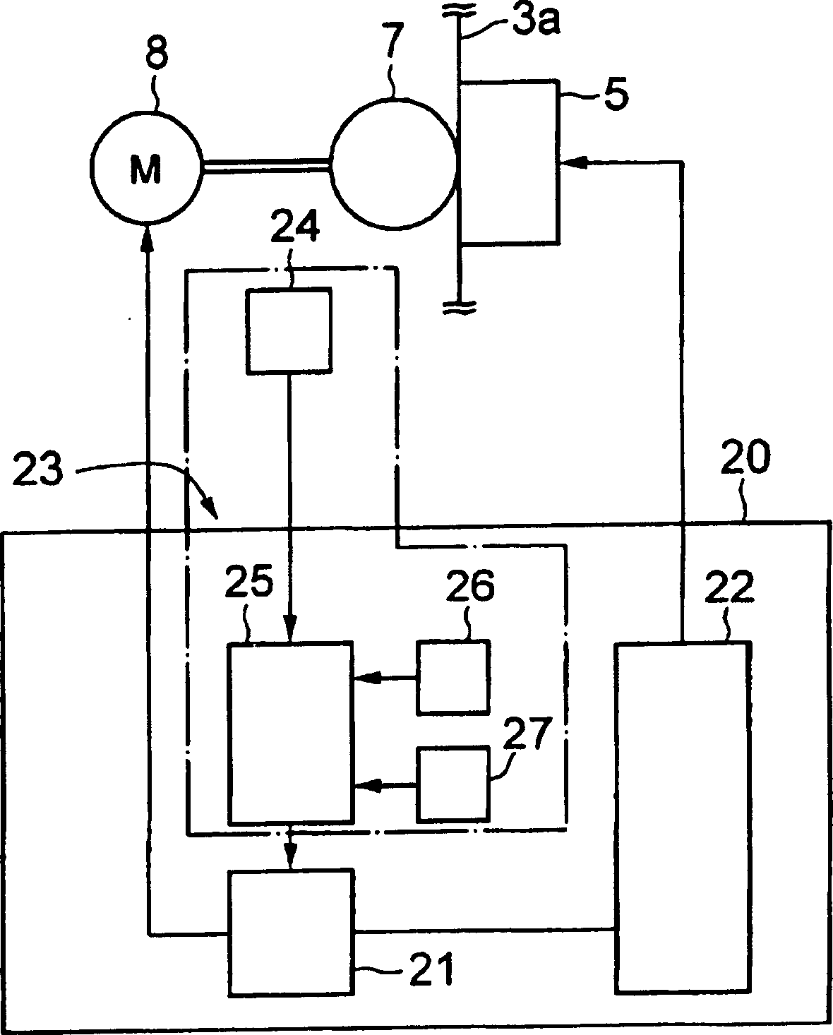
To provide a thermal printer in which printing is carried out at a constant line interval while employing a DC motor as the power source for feeding a recording sheet.The printer comprises a sheet feed control section 25 including a unit 6 for feeding a recording sheet 3a using a DC motor 8 as a power source, a print head 5 for printing on the recording sheet 3a being fed, and a section 23 for detecting the feeding amount of the recording sheet 3a and controlling the DC motor 8, and a print control section 24 for controlling the print head 5. Feeding amount b of sheet is detected after stopping power supply to the DC motor 8 before feeding of the recording sheet 3a is stopped. Subsequent printing is started after starting power supply to the DC motor 8 and feeding the sheet by an amount (a) determined by subtracting the sheet feeding amount b from a specified interline sheet feed amount c thus performing printing at a constant line interval. (C)2005,JPO&NCIPI.
Description
technical field [0001] The present invention relates to a line printer that uses a DC motor as a drive source to feed recording paper. Background technique [0002] As a power source for feeding paper in a printer, various forms such as a stepping motor and a DC motor are known. A DC motor has the advantage of being able to reduce manufacturing costs compared to the case of using a stepping motor. For example, an example is described in which a DC motor is used instead of a stepping motor as a power source for paper feeding in a thermal printer having a thermal print head. (Japanese Patent Application Laid-Open No. 11-291535) [0003] However, this DC motor does not have a rapid rise characteristic at the start of driving, or a rapid stop characteristic at the stop of driving, compared with a stepping motor. Therefore, when a DC motor is used as the power source for feeding the recording paper, in order to end the printing of the recording paper and stop the feeding of th...
Claims
Login to View More Application Information
Patent Timeline
 IPC IPC(8): B41J11/42B41J2/315B41J2/355B41J15/04
Inventor二木英俊
OwnerSEIKO EPSON CORP