Typewriter letter hammer group with magnetic shunt

A technology of magnetic shunt and hammer printing, applied in hammer printing mechanism, printing device, printing, etc., can solve the problem of increasing the starting speed of impact energy, and achieve the effect of large pull-down force or holding force, and large impact energy

Active Publication Date: 2004-09-08
PRINTRONIX LLC
View PDF0 Cites 4 Cited by
  • Summary
  • Abstract
  • Description
  • Claims
  • Application Information

AI Technical Summary

Problems solved by technology

The end result is an increase in impact energ

Method used


Image

  • Typewriter letter hammer group with magnetic shunt
  • Typewriter letter hammer group with magnetic shunt
  • Typewriter letter hammer group with magnetic shunt

Examples


Embodiment Construction

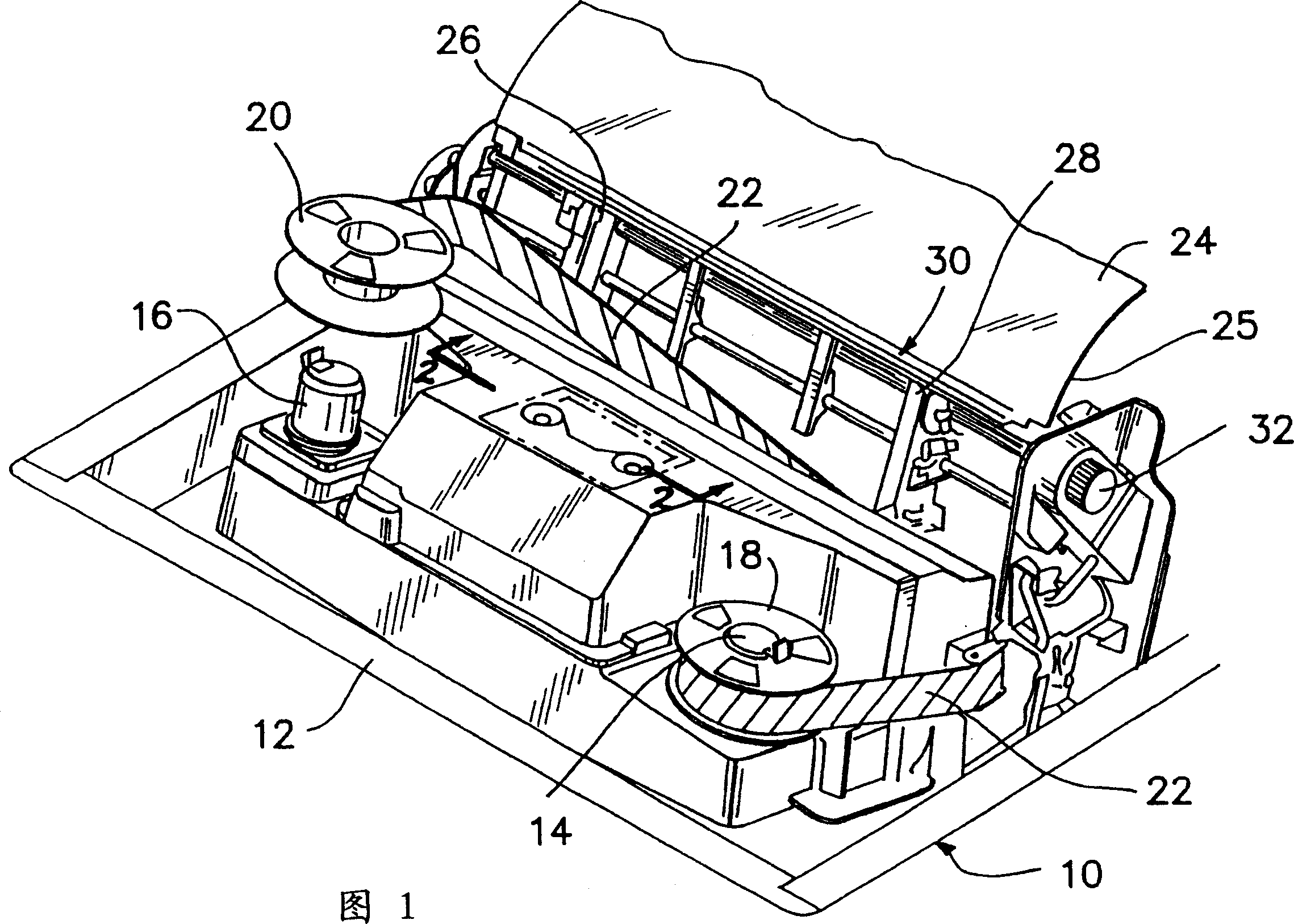
[0024] Referring to Figure 1 in more detail, a perspective view of a line matrix printer is illustrated. The line printer can be mounted on a base, substrate or combined with a housing. In this particular illustration, the line matrix printer 10 has a base 12 . The base 12 mounts various elements of the line printer including hubs 14 and 16 . Axles 14 and 16 are used to mount spools 18 and 20 . Spools 18 and 20 are a supply ribbon spool and a take-up spool, respectively.

[0025] Wrapped around spools 18 and 20 is a print ribbon 22 for printing on media 24 .

[0026] The medium 24 covers the support plate 25 . Such media may be fan-folded, barcode labels, combined plastic and paper labels and formats, paper media for images, and other such media. Depending on the thickness of the media 24, the high impact printing developed in the present invention can improve multi-form and multi-layer printing through improved impact. Also, depending on the speed required to print on t...


PUM


Abstract

An impact line printer comprising a print ribbon wound on a pair of spools for traversal in two directions across a plurality of print hammers having tips for impacting the print ribbon to print on a media. A permanent magnet having two pole pieces having pole piece ends in adjacent relationship to the print hammers retains the print hammers until a coil in associated relationship with each pole piece releases the magnetic retention of the hammers. A magnetically permeable extension is longitudinally adjacent each hammer which acts as a magnetic shunt to permit more rapid printing rates and higher impacts. The extensions conduct and shunt magnetic flux from the hammers through the longitudinally adjacent extensions.

Description

technical field [0001] The present invention relates to the technical field of impact printing. Impact printing can be done by having a protruding hammer whose tip strikes the ribbon to form a series of dots or dot pattern on the underlying media. The present invention more particularly relates directly to a line printer hammerset having a series of hammers held by permanent magnets and released for striking by an electric coil overcoming the permanent magnets. Background technique [0002] The prior art relating to impact printers generally presents impact printers of many different designs and configurations. One of the preferred types of impact printers are those known as line matrix printers. A line matrix printer is constructed in which a hammer set having a plurality of printing tips strikes a printing ribbon covering the medium to be printed on. The hammer is controlled and held by a permanent magnet until released for striking. In order to hold the hammer, the pe...

Claims


Application Information

Patent Timeline
IPC IPC(8): B41J9/38
CPCB41J9/38
Inventor 约翰·W·格默尔
Owner PRINTRONIX LLC
Why Eureka
Try Eureka