Recording device, method of controlling a recording device, and recording medium

a recording device and recording medium technology, applied in the direction of instruments, visual presentations, computing, etc., can solve the problems of inaccurate and inconvenient control of the motor to rise from a stop to a constant speed, inconvenient operation, and inability to accurately control the motor, so as to achieve efficient execution of job-related processes

Inactive Publication Date: 2012-09-20
SEIKO EPSON CORP
View PDF5 Cites 3 Cited by
  • Summary
  • Abstract
  • Description
  • Claims
  • Application Information

AI Technical Summary

Benefits of technology

[0038]The invention enables efficiently executing job-related processes for jobs input from a control device.

Problems solved by technology

When the foregoing recording device with a print head continuously receives a plurality of jobs and executes the jobs sequentially, the process related to the jobs needs to be performed as efficiently as possible, but a suitable solution to this problem has not been proposed.
Because conveyance precision is required when using a printhead, and particularly an inkjet head, the acceleration and deceleration control required for the motor to rise from a stop to a constant speed is complicated and time-consuming, and require conveying the recording medium.
In addition, if conveyance does not stop at an appropriate position between images, instead of on an image, when waiting for signals from the control device and during regular head cleaning, for example, mechanical error will be apparent where conveyance stops, precise conveyance will be disrupted, and image quality will drop.
In addition, if recording starts every time receiving a job starts, operation will soon stop to wait for the next job because the recording process is fast once the rated speed is reached.

Method used


Image

  • Recording device, method of controlling a recording device, and recording medium
  • Recording device, method of controlling a recording device, and recording medium
  • Recording device, method of controlling a recording device, and recording medium

Examples


example 1

[0115]FIG. 5 is a flow chart showing the operation of the inkjet line printer 1 and host computer 25 in example 1. FIG. 5(A) shows the operation of the host computer 25, and FIG. 5(B) shows the operation of the inkjet line printer 1.

[0116]The processes related to job execution are performed efficiently using a simpler process in example 1 than in example 2 described below.

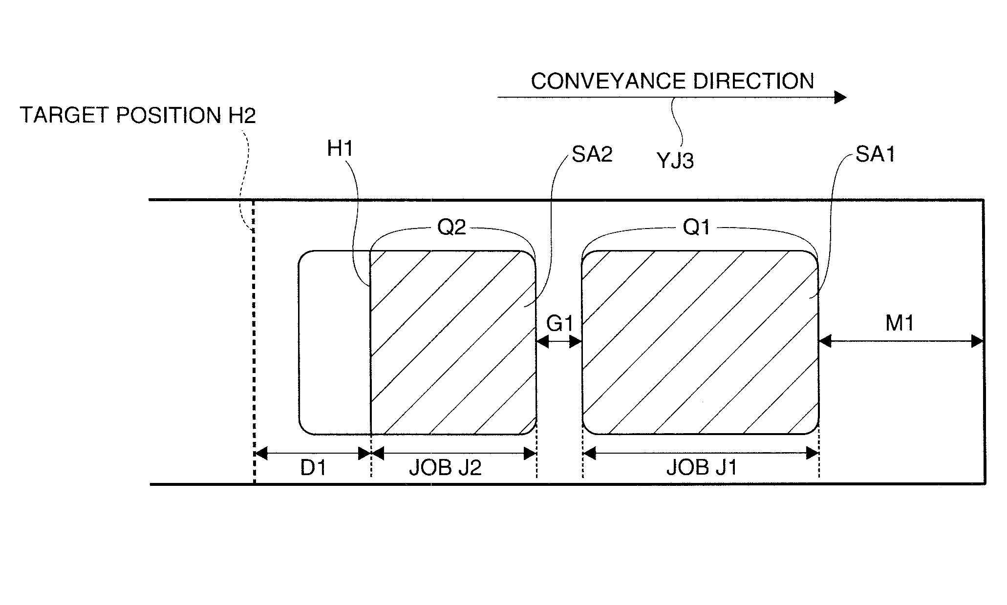
[0117]In example 1 described next, job J1 related to recording an image to area SA1 of seal part S1, and job J2 related to recording an image to area SA2 of seal part S2, are input sequentially from the host computer 25 to the inkjet line printer 1, and the inkjet line printer 1 sequentially executes the input job J1 and job J2 as shown in FIG. 4.

[0118]Note also that in the flow chart shown in FIG. 5 the functions of the information output unit 55 and printer-side control unit 27 are achieved by the cooperation of hardware and software, such as by a CPU executing a specific program.

[0119]As shown in FIG. 5, before ...

example 2

[0136]FIG. 7 is a flow chart showing the operation of the inkjet line printer 1 and host computer 25 in example 2. (A) in FIG. 7 shows the operation of the host computer 25, and (B) in FIG. 7 shows the operation of the inkjet line printer 1.

[0137]As in example 1, in example 2 job J1 related to recording an image to area SA1 of seal part S1, and job J2 related to recording an image to area SA2 of seal part S2, are input sequentially from the host computer 25 to the inkjet line printer 1, and the inkjet line printer 1 sequentially executes the input job J1 and job J2.

[0138]As shown in FIG. 7, the information output unit 55 of the host computer 25 outputs job-related information to the inkjet line printer 1 before outputting the jobs (step SC1).

[0139]This job-related information includes at least information indicating the number of jobs scheduled to be output, the data transfer rate of communications between the host computer 25 and the inkjet line printer 1, the amount of data in the...


PUM


Abstract

Processes related to jobs received from a control device can be executed efficiently. An inkjet line printer 1 has a printer-side control unit 27 that, when receiving jobs, gets job-related information related to the received jobs from a host computer 25, and based on the acquired job-related information determines the sequence of processes related to executing the received jobs.

Description

[0001]This application claims priority under 35 U. S. C. §119 to Japanese Patent Application No. 2011-57684 filed on Mar. 16, 2011, the entire disclosure of which is expressly incorporated by reference herein.BACKGROUND[0002]1. Technical Field[0003]The present invention relates to a recording device that records by a print head (printhead) on a recording medium conveyed in a conveyance direction, to a method of controlling the recording device, and to a recording medium storing a program for controlling the recording device.[0004]2. Related Art[0005]Recording devices that record images by a print head such as a inkjet head on a recording medium conveyed in a conveyance direction are known from the literature. See, for example, Japanese Unexamined Patent Appl. Pub. JP-A-2010-12625.[0006]When the foregoing recording device with a print head continuously receives a plurality of jobs and executes the jobs sequentially, the process related to the jobs needs to be performed as efficiently...

Claims


Application Information

Patent Timeline
Patent Type & Authority Applications(United States)
IPC IPC(8): G06K15/16
CPCG06K15/024G06K15/1809G06K15/16
Inventor NEGISHI, KEIKO
Owner SEIKO EPSON CORP
Why Eureka
Try Eureka