Line printer and printhead moving method of a line printer

Active Publication Date: 2016-03-22
SEIKO EPSON CORP
View PDF11 Cites 3 Cited by
  • Summary
  • Abstract
  • Description
  • Claims
  • Application Information

AI Technical Summary

Benefits of technology

[0012]A line printer and a printhead moving method of a line printer according to at least one embodiment of the invention prevent the printhead from colliding with a member such as a media separation prevention member disposed above the platen when a p

Problems solved by technology

Therefore, when the printhead is then returned to the position opposite the platen, the printhead and the recording paper can collide, easily resulting in damage to the printhead or a paper jam.
However, when such a media separation prevention member is provided, the media separation prevention member and the printhead may collid

Method used


Image

  • Line printer and printhead moving method of a line printer
  • Line printer and printhead moving method of a line printer
  • Line printer and printhead moving method of a line printer

Examples


Embodiment Construction

[0060]A preferred embodiment of a line printer according to the present invention is described below with reference to the accompanying figures.

General Configuration

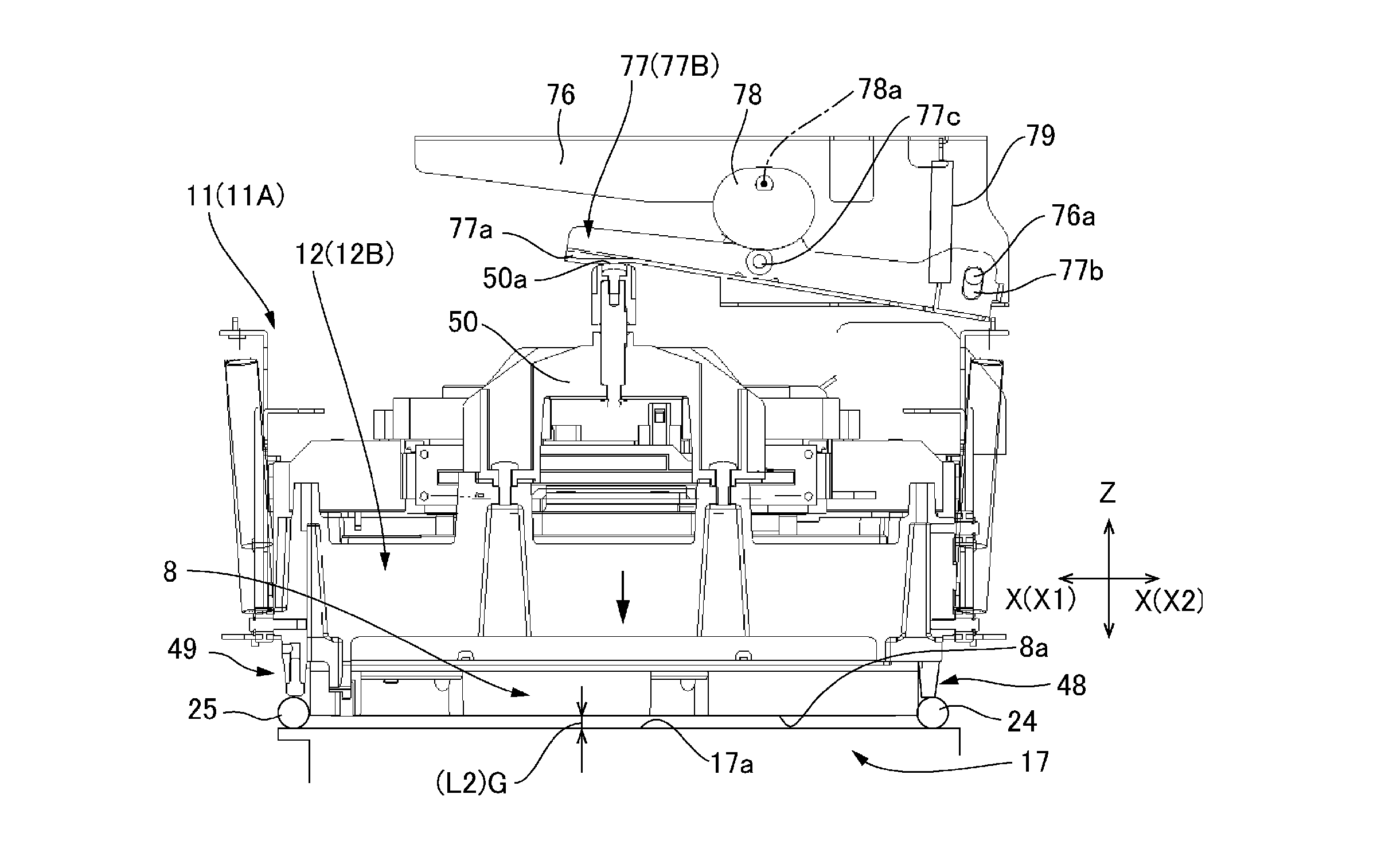
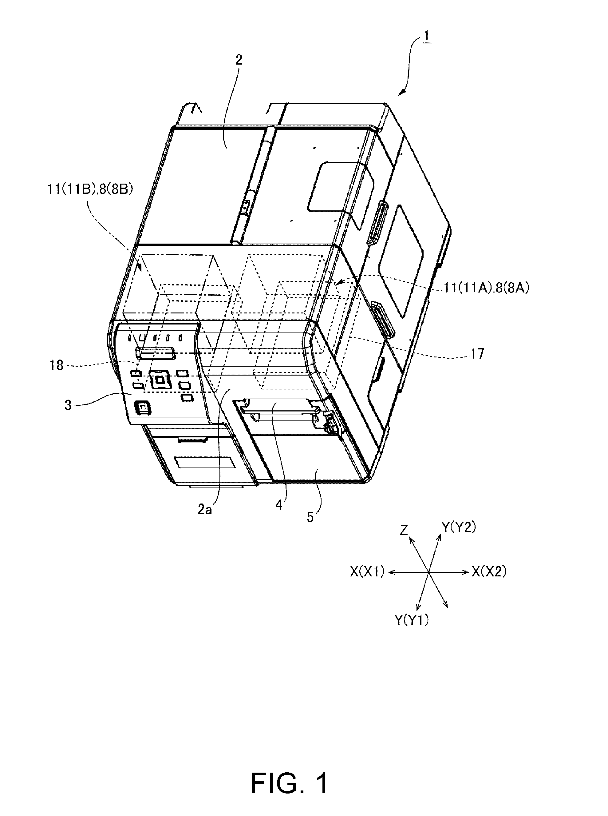
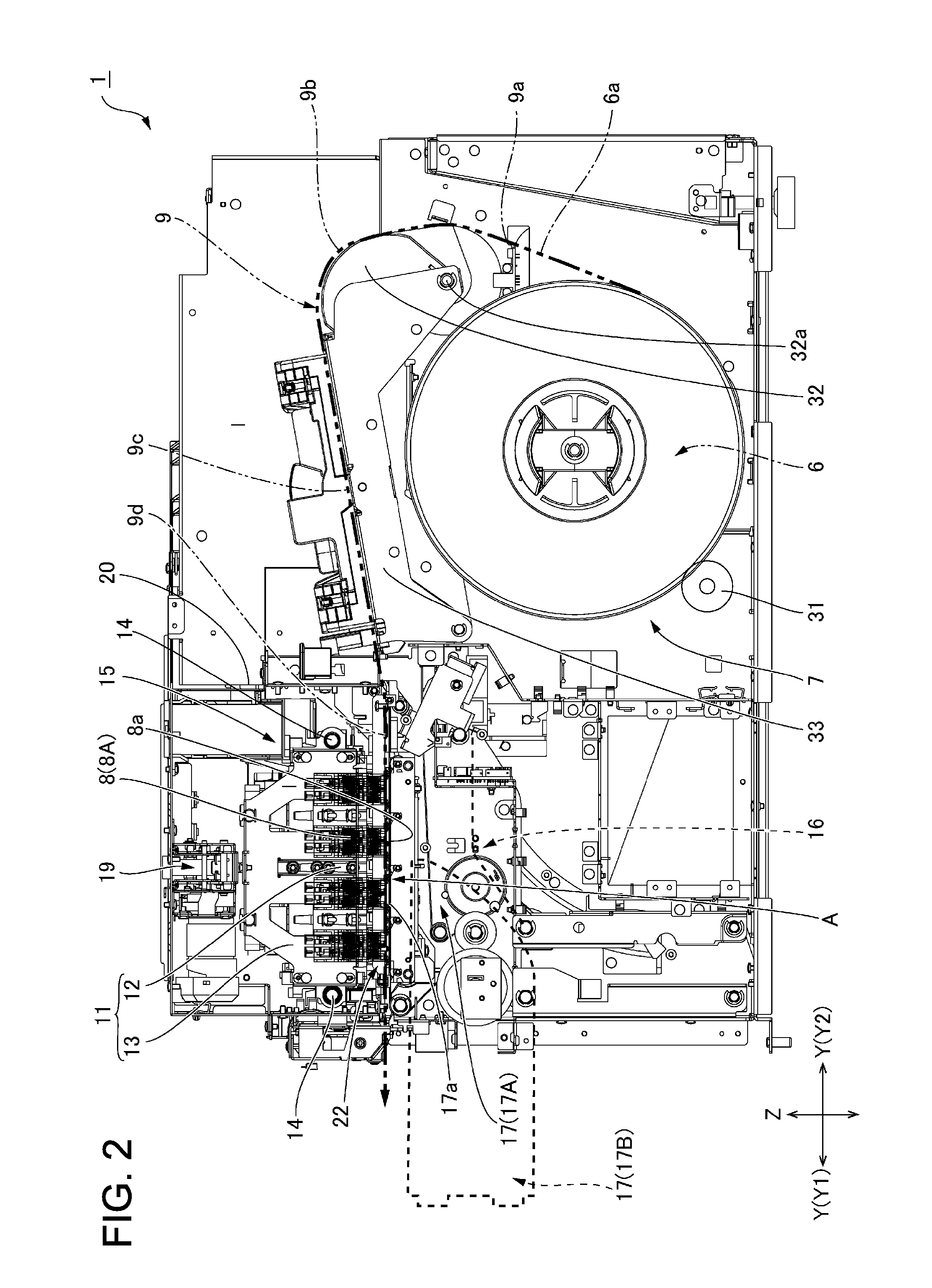
[0061]FIG. 1 is an external oblique view of a line printer according to the invention. FIG. 2 is a vertical section view showing the internal configuration of the line printer.

[0062]As shown in FIG. 1, the line printer 1 has a printer cabinet 2 that is basically box-shaped and is long from front to back. An operating panel 3 is disposed to one side of the transverse axis X at the top of the front 2a of the printer cabinet 2, and a paper exit 4 is formed on the other side. An access cover 5 for maintenance is disposed below the paper exit 4.

[0063]As shown in FIG. 1, the invention is described below with reference to three mutually perpendicular directional axes, the transverse axis X across the device width, a longitudinal axis Y, and a vertical axis Z.

[0064]As shown in FIG. 2, a roll paper compartment 7 for holding a pap...


PUM


Abstract

The carriage of a line printer has a head unit that supports a printhead, and a carriage frame that supports the head unit movably up and down. When moving the carriage from a standby position to an opposing position, the carriage is moved while the head unit is held at a up position where the gap to the platen unit is a first distance. The head unit is then lowered at the standby position from the up position to a down position where the platen gap is a second distance that is shorter than the first distance.

Description

[0001]Priority is claimed under 35 U.S.C. §119 to Japanese Application Nos. 2013-225052 and 2013-233737 filed on Oct. 30, 2013 and Nov. 12, 2013, respectively, both of which are incorporated in their entireties.BACKGROUND[0002]1. Technical Field[0003]The present disclosure relates to a line printer that moves the printhead between a position opposite the platen and a position removed to the side from the position opposite the platen, and to a method of moving a printhead in a line printer.[0004]2. Related Art[0005]A line printer that prints on recording paper conveyed at a constant speed over a platen is described in JP-A-2011-025479. The line printer in JP-A-2011-025479 uses an inkjet head as the printhead. The printhead is configured from a set of four inkjet line heads that respectively eject ink droplets of cyan, black, magenta, and yellow ink, and each inkjet line head is wider than the recording paper. The four inkjet line heads are disposed with a specific gap therebetween in...

Claims


Application Information

Patent Timeline
IPC IPC(8): B41J25/34B41J25/308B41J25/304B41J2/165
CPCB41J25/34B41J2/16588B41J25/304B41J25/3084B41J25/24B41J25/001
Inventor NAGATA, NORIOMAEKAWA, HIRONORIAOKI, TAKASHIHIRASHIMA, TAKU
Owner SEIKO EPSON CORP
Why Eureka
Try Eureka