Backlight module

A technology of backlight module and light source group, which is applied in the direction of light source, optical light source, electric light source, etc., and can solve the problems of uneven light mixing in the backlight module 10, affecting the luminous quality of the backlight module, and reddish color, etc.

Inactive Publication Date: 2004-11-10
AU OPTRONICS CORP
View PDF0 Cites 16 Cited by
  • Summary
  • Abstract
  • Description
  • Claims
  • Application Information

AI Technical Summary

Problems solved by technology

[0006] However, when the LED array 16 generates light, since the light source group in row 1 with several red LEDs and the light source group in row 3N with several blue LEDs are adjacent to the first side 14b and the first side 14b and the first row respectively The two sides 14c cause the backlight module 10 to mix light unevenly, and produce reddish and bluish colors in the liquid crystal display panels corresponding to the first side 14b and the second side 14c respectively, that is, the so-called Color cast
Therefore, traditionally, as long as the LED array is composed of LEDs of different colors, uneven light mixing and color shift will occur in the liquid crystal display panel corresponding to the side of the circuit board, which will affect the luminous quality of the backlight module. very large

Method used


Image

  • Backlight module
  • Backlight module
  • Backlight module

Examples


Embodiment 1

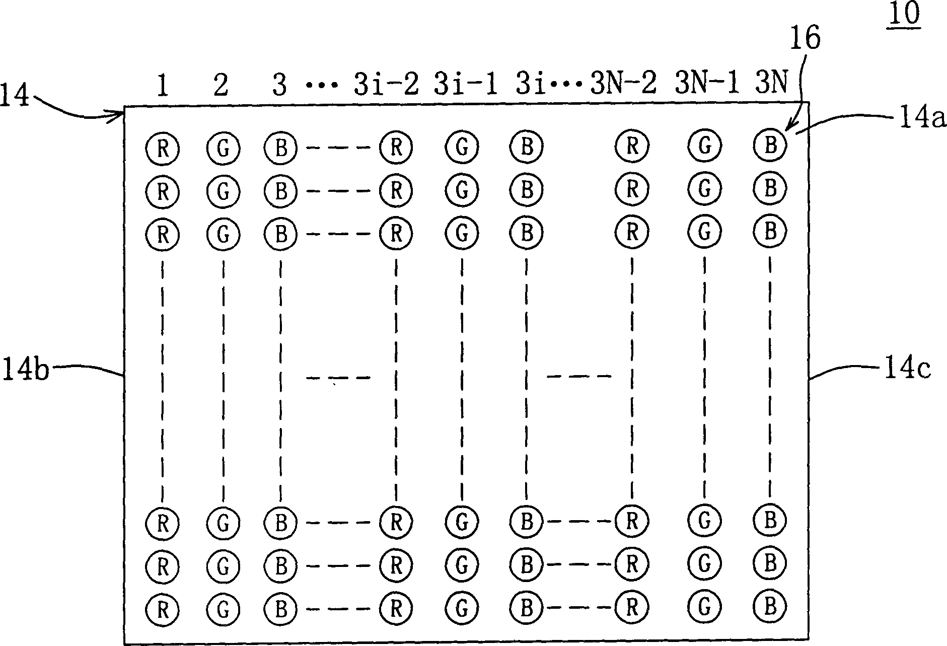
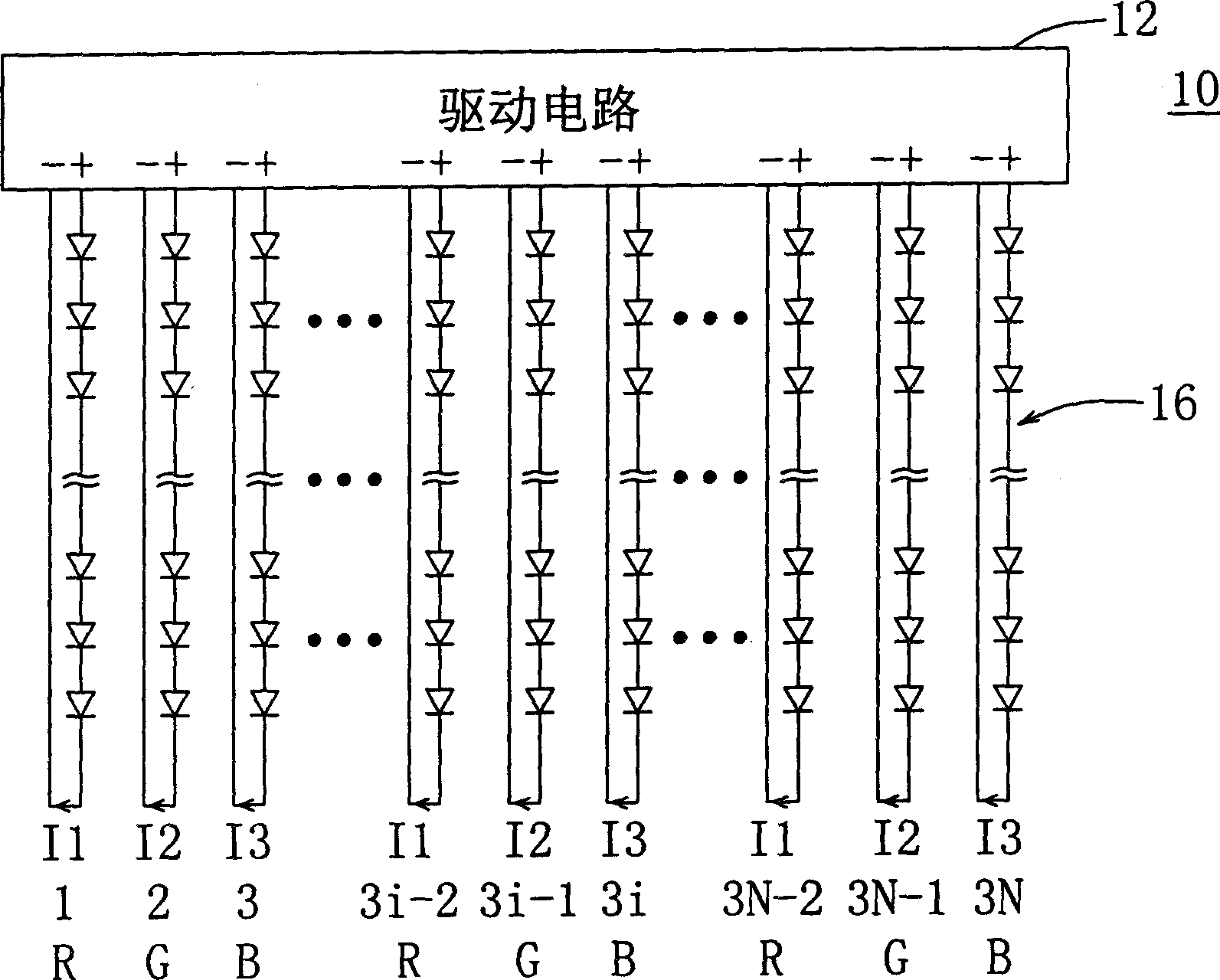
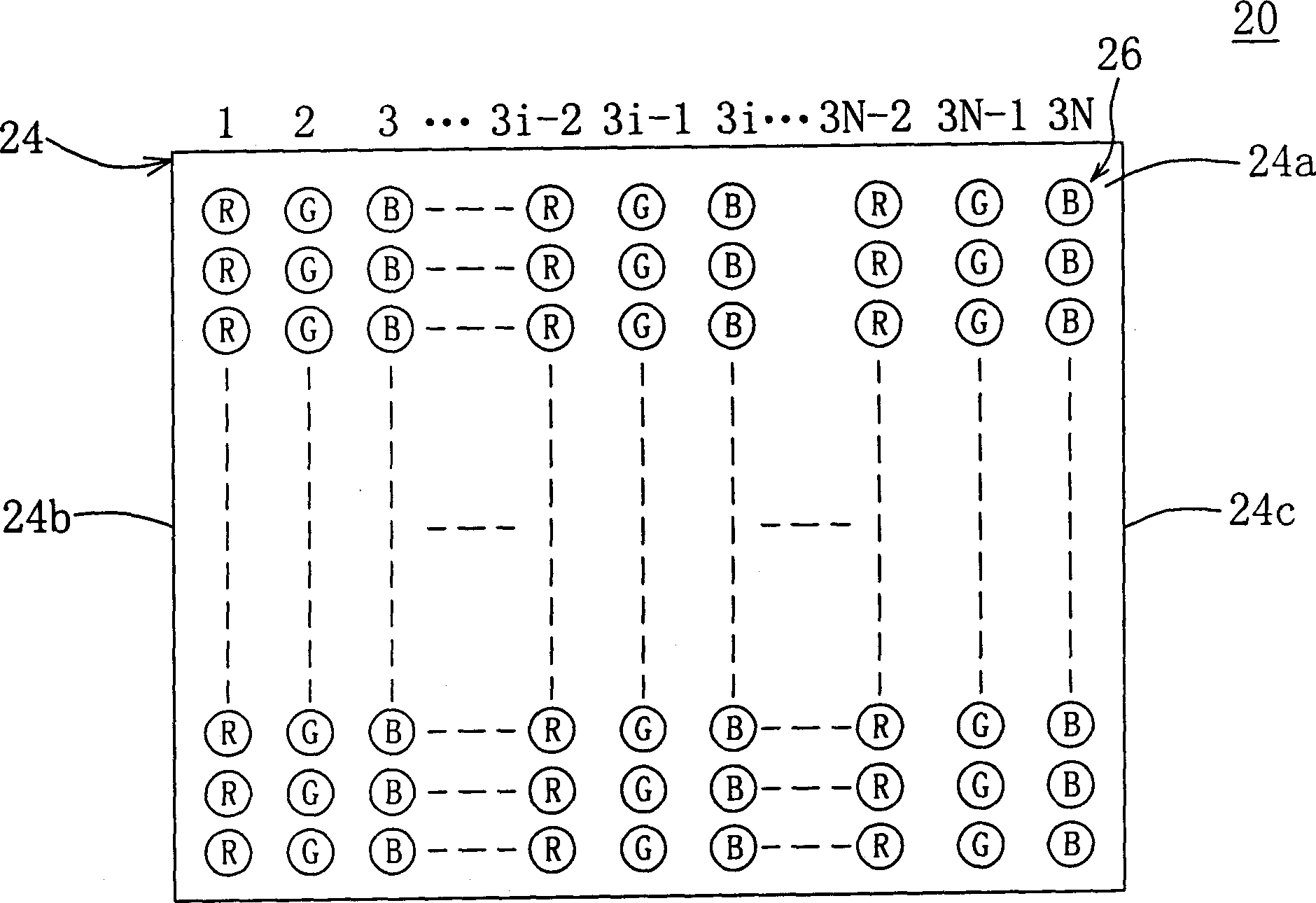
[0020] Please refer to Figure 2A and Figure 2B , Figure 2A A partial top view of a backlight module according to Embodiment 1 of the present invention is shown, Figure 2B A partial equivalent circuit diagram of the backlight module according to Embodiment 1 of the present invention is shown. exist Figure 2A and Figure 2B Among them, the backlight module 20 at least includes a driving circuit 22 , a circuit board 24 and a light emitting diode array (light emitting diode, LED) 26 . The circuit board 24 has opposite first side 24b and second side 24c and a top surface 24a connecting the first side 24b and the second side 24c. The light emitting diode array 26 is arranged on the top surface 24a of the circuit board 24. The light emitting diode array 26 has several rows of light source groups. Here, 3N rows of light source groups are used as an example for illustration. The first row of light source groups and the 3N row of light source groups are adjacent to each other....

Embodiment 2

[0028] Please refer to image 3 , which shows a partial equivalent circuit diagram of the backlight module according to Embodiment 2 of the present invention. exist image 3 Among them, the difference between the backlight module 30 of this embodiment and the backlight module 20 of the first embodiment is that the backlight module 30 includes driving circuits 32a, 32b, 32c, 32d, 32e, 32f and 32g. As for the similarity between the backlight module 30 and the backlight module 20 of the first embodiment, for example, the light emitting diode array 26 is arranged on Figure 2A The arrangement on the top surface 24a of the circuit board 24 will not be repeated here.

[0029] The driving circuit 32a provides a current I33 to the light source group in row 3N or the corresponding first LEDs, and the driving circuit 32e provides a current I31 to the light source group in the third row or the corresponding first LEDs. The driving circuit 32c provides the current I32 to the light sour...

Embodiment 3

[0032] Please refer to Figure 4 , which shows a partial equivalent circuit diagram of the backlight module according to Embodiment 3 of the present invention. exist Figure 4 Among them, the difference between the backlight module 40 of this embodiment and the backlight module 20 of the first embodiment is that the backlight module 40 includes a driving circuit 42 and current limiting resistors R1 , R2 , R3 and R4 . As for the similarities between the backlight module 40 and the backlight module 20 of Embodiment 1, for example, the light emitting diode array 26 is arranged on Figure 2A The arrangement on the top surface 24a of the circuit board 24 will not be repeated here.

[0033] The driving circuit 42 provides a voltage V1 to the light source groups in the row 3i of the LED array 26, and the current limiting resistor R1 is electrically connected to the driving circuit 42 and the light source groups in the row 3j, or the current limiting resistor R1 is electrically conn...


PUM


Abstract

The invention relates to a backlight module, including circuit board, LED array and driving circuit. The LED array is set on the circuit board and has 3N lines of light source groups, where the first line of light source group and 3Nth line of light source group are adjacent to two sides of the circuit board, respectively, and each line has several LEDs. The driving circuit provides current for the LED array, to make the brightness of each LED of the 3Nth line is less than that of the third line, and the brightness of each LED of the first line is less than that of the 3N-2th line.

Description

technical field [0001] The present invention relates to a backlight module, and in particular to a backlight module using a light emitting diode (light emitting diode, LED) array as a light source. Background technique [0002] With the rapid progress of liquid crystal display (liquid crystal display, LCD) production technology, and its advantages of lightness, lightness, power saving, and radiation-free, the liquid crystal display is widely used in personal digital assistants (personal digital assistants, PDAs). ), notebook computers, digital cameras, digital video recorders, mobile phones, computer screens and LCD TVs and other electronic products. Coupled with the industry's active investment in research and development and the adoption of large-scale production equipment, the quality of liquid crystal displays has been continuously improved, and the price has been continuously reduced, thus rapidly expanding the application field of liquid crystal displays. However, sin...

Claims


Application Information

Patent Timeline
Patent Type & Authority Applications(China)
IPC IPC(8): G02F1/13357H05B37/02
Inventor 刘邦炫周晖凯
Owner AU OPTRONICS CORP
Why Eureka
Try Eureka