
Electric vacuum cleaner head and electric vacuum cleaner using same

A vacuum cleaner, electric technology, applied in the direction of vacuum cleaners, suction nozzles, applications, etc., can solve problems such as difficult cleaning, narrow gaps, complex structures, etc., and achieve high wiping effect

Inactive Publication Date: 2004-12-01
PANASONIC CORP
View PDF1 Cites 2 Cited by
  • Summary
  • Abstract
  • Description
  • Claims
  • Application Information

AI Technical Summary

Problems solved by technology

[0003] However, in the above-mentioned existing suction head, since a driving source for rotating the rotatable flannelette needs to be provided inside, the size of the suction head will become larger and the weight will also increase.
In addition, since mechanisms such as transmission belts or gears need to be provided, there are problems of complex structure and high cost.
[0004] In addition, since the rotating flannel is parallel to the length direction of the suction head, there is a problem that it is difficult to clean the narrow gap

Method used


Image

  • Electric vacuum cleaner head and electric vacuum cleaner using same
  • Electric vacuum cleaner head and electric vacuum cleaner using same
  • Electric vacuum cleaner head and electric vacuum cleaner using same

Examples


Embodiment Construction

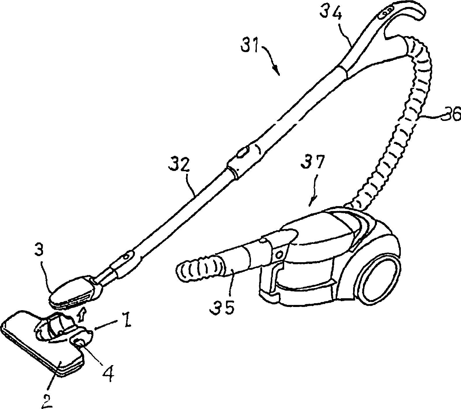
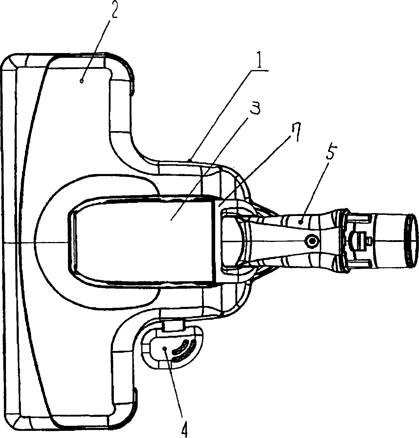
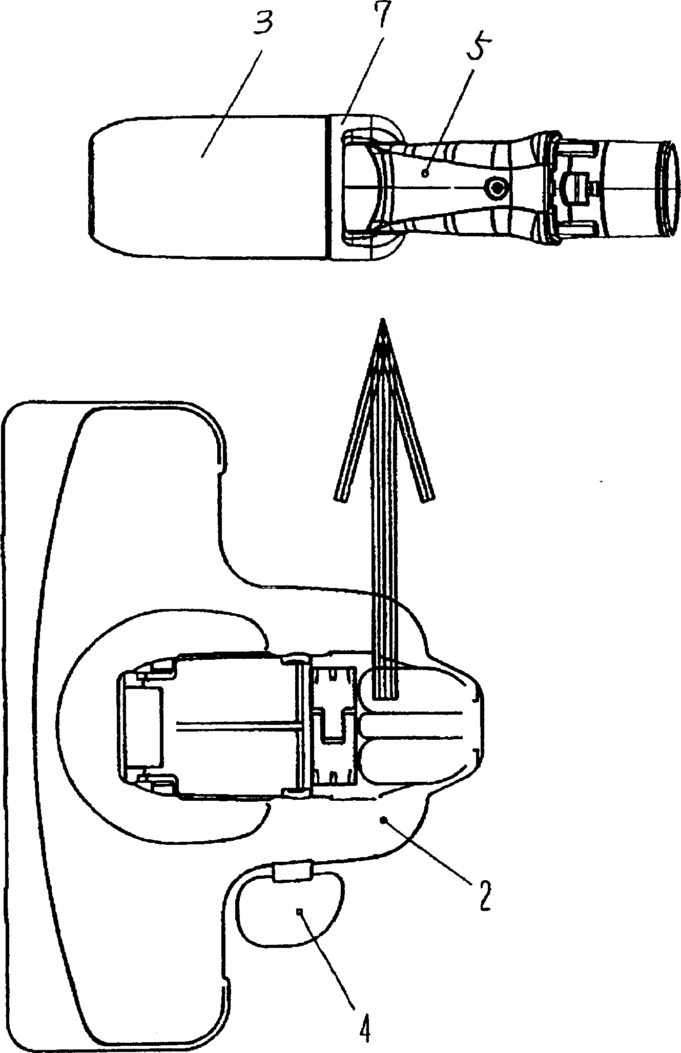
[0033] With the help of Figure 1 to Figure 8 An embodiment of the present invention will be described.

[0034] exist figure 1 Among them, the reference numeral 37 is a ground mobile electric vacuum cleaner, which is provided with a suction part 2 for attracting dust and a suction head 3 which can be detachably attached to the suction part 2 . The suction head 3 is installed on the front end of the extension tube 32 in a detachable manner, and the extension tube 32 is connected with the handle armrest 34 . One end of the hose 36 is connected with the handle armrest 34 , and the other end is connected with the main body 37 of the vacuum cleaner through a hose joint 35 .

[0035] In addition, the suction part 2 and the suction head 3 can suck the dust on the surface to be cleaned when the suction head 3 is installed on the suction part 2, or the pedal 4 can be operated to remove the suction head 3 from the suction part 2. Next, the dust on the surface to be cleaned is sucked...


PUM


Abstract

Provided is a small-size, lightweight and low cost suction device for a vacuum cleaner having superior sweeping and polishing performances. This suction device is provided with a downward opening suction port 15 and rotors 10 facing to the suction port 15 and rotatably provided therein, and the longitudinal central axes L of the rotors 10 are disposed in approximately parallel to the front / rear direction of the body of the suction device 3. This suction device 3 can be thus formed long in the front / rear direction so as to facilitate the cleaning in a narrow place and the rotors 10 can provide the suction device with the high wiping, sweeping and polishing performances. This constitution can provide the small-size, lightweight, and low cost suction device for the vacuum cleaner having high wiping, sweeping and polishing performances and superior maintenanceability.

Description

technical field [0001] The invention relates to a suction head of an electric vacuum cleaner for attracting dust and an electric vacuum cleaner using the suction head. Background technique [0002] Among the existing suction heads of electric vacuum cleaners, some of them are provided with a horizontally rotating flannelette with extremely fine microfibers in the suction port, and can rotate freely with the help of the driving roller and the driven roller inside it. The driving source for the rotation of the driving drum. If the suction head with this structure is used, soft elasticity can be applied to the surface to be cleaned, and it can play the same role as a rag through extremely soft contact, without damaging the surface to be cleaned, and at the same time it can play a role in cleaning the surface. The function of wiping, cleaning and polishing. The cleaning operation can be completed with very high efficiency in a short period of time for the surface to be cleaned...

Claims


Application Information

Patent Timeline
Patent Type & Authority Applications(China)
IPC IPC(8): A47L9/04A47L5/00A47L9/06
Inventor 藤田孝一副岛雅邦澁谷昌树
Owner PANASONIC CORP
Learn More