Magnetic rotation detector, relative vehicle control device and method for judging abnormal of roter

A technology of vehicle control devices and detectors, applied to devices using electric/magnetic methods, measuring devices, conversion sensor outputs, etc., which can solve problems such as fluctuations in wrong speeds

Inactive Publication Date: 2004-12-01
TOYOTA JIDOSHA KK +1
View PDF1 Cites 9 Cited by
  • Summary
  • Abstract
  • Description
  • Claims
  • Application Information

AI Technical Summary

Problems solved by technology

If the change in magnetic flux is disturbed in this way, even if the rotor itself turns at a constant speed, fluctuations in rotational speed will be falsely detected

Method used


Image

  • Magnetic rotation detector, relative vehicle control device and method for judging abnormal of roter
  • Magnetic rotation detector, relative vehicle control device and method for judging abnormal of roter
  • Magnetic rotation detector, relative vehicle control device and method for judging abnormal of roter

Examples


Embodiment Construction

[0022] Preferred embodiments of the present invention will be described in detail below with reference to the accompanying drawings. To facilitate understanding of the following description, like reference numerals are used as much as possible to denote similar components in the drawings, and repetition of the same description will be avoided.

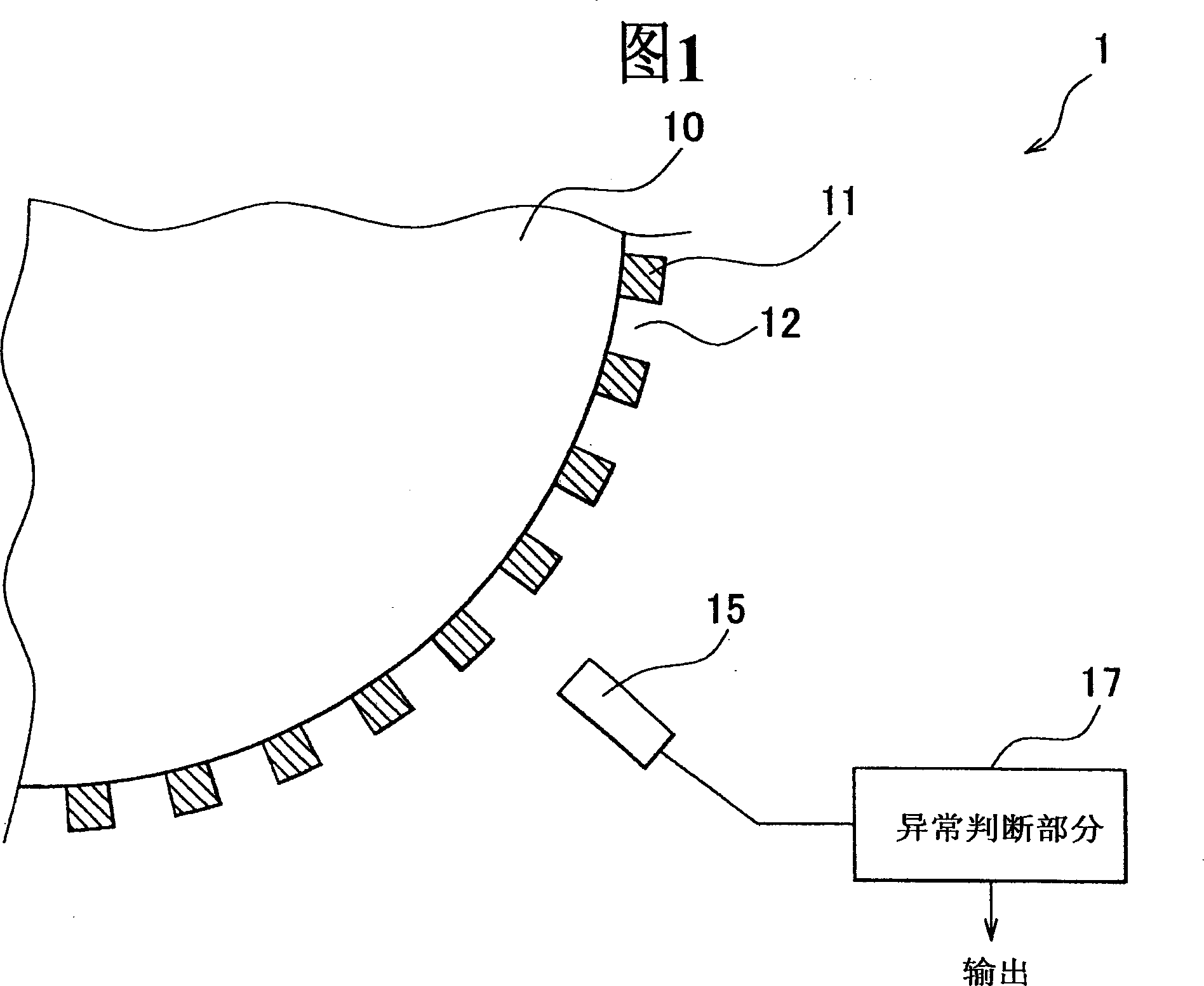
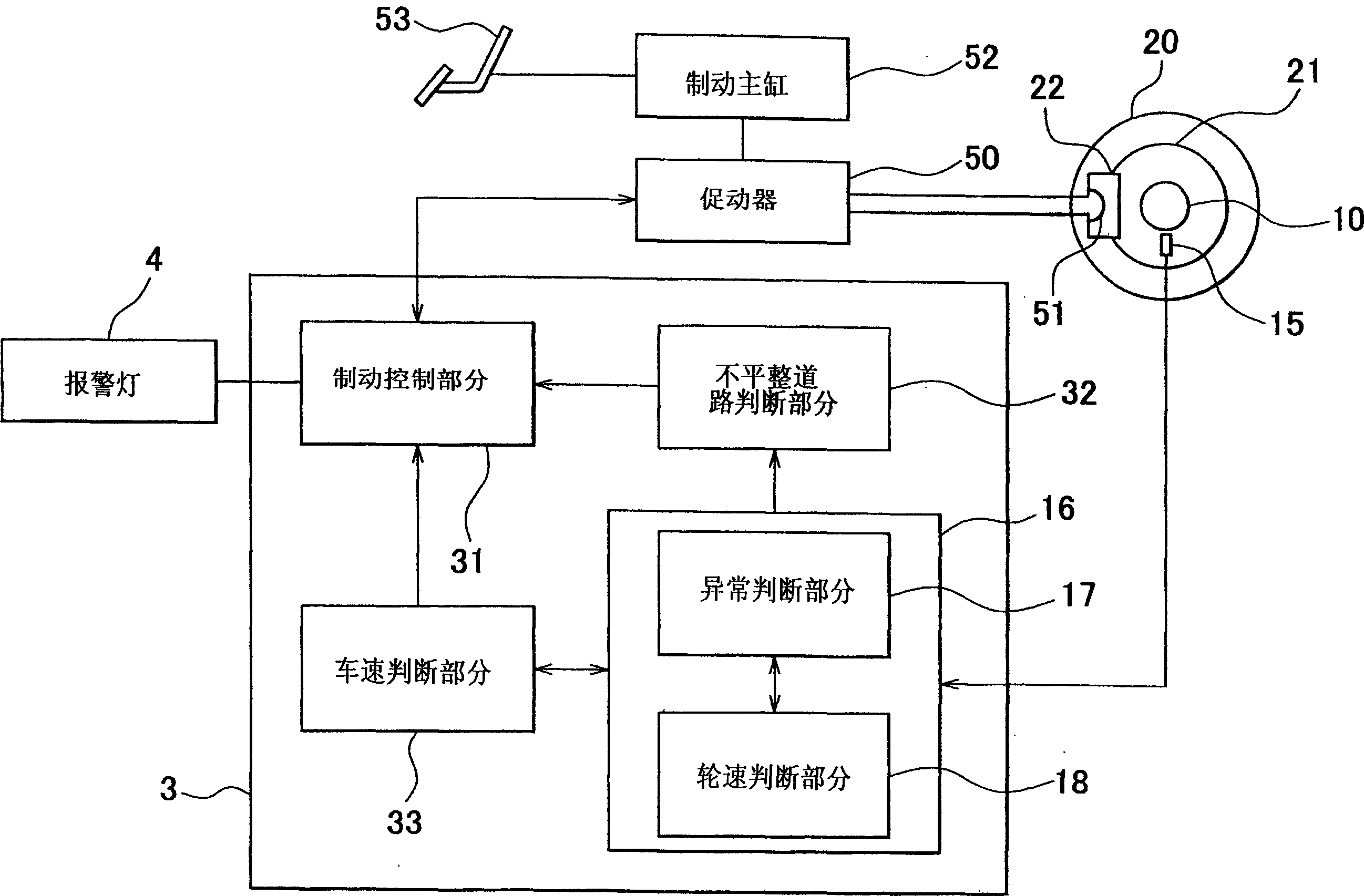
[0023] FIG. 1 is a schematic diagram of a magnetic rotation detector according to an embodiment of the present invention. It should be noted here that only a part of the magnetic rotor 10 is shown in FIG. 1 . The magnetic rotor 10 is disc-shaped. The magnets 11 are arranged at equal intervals on the outer circumference of the magnetic rotor 10 while protruding therefrom. Each gap 12 is formed between adjacent magnets 11 . A sensor (detection body) 15 is adjacent to the outer peripheral surface of the magnetic rotor 10 and is fixed at a position where the sensor 15 is at rest when the magnetic rotor 10 rotates. For the sensor 15, va...


PUM


Abstract

Magnetic flux change around a pickup 15 generated by moving a magnet 11 arranged on the periphery of the magnetic rotor 10 is detected by the pickup 15 following rotation of the magnetic rotor 10. It is determined as an abnormal state of the magnetic rotor 10 such as iron piece attraction onto the magnet 11, when the output fluctuation is generated by the magnet 11 on a specific position of the magnetic rotor 10.

Description

technical field [0001] The present invention relates to a magnetic rotation detector for detecting a rotational speed of a wheel, a vehicle control device using the magnetic rotation detector, and a method of judging an abnormality in a magnetic rotor. Background technique [0002] A magnetic rotation sensor is known as a device for detecting the rotation speed of a wheel in a vehicle (for example, see Japanese Patent Application Laid-Open No. 3-59416 (pages 3 and 4, FIG. 1)). This magnetic rotation sensor consists of a magnet and a detector. The magnets are arranged at equal intervals on the outer peripheral portion of the rotor, which rotates synchronously with an object whose rotational speed is to be detected. The detector is a sensor such as a Hall device, and is disposed on the outside of the rotor and faces the rotor. If the rotor rotates, magnets disposed on the outer circumference of the rotor cause a change in magnetic flux around the sensor. The sensor detects ...

Claims


Application Information

Patent Timeline
Patent Type & Authority Applications(China)
IPC IPC(8): G01P3/42B60T8/171B60T8/66B60T8/88G01D5/245G01P3/487G01P3/489G01P21/02
CPCG01P21/02G01P3/489G01P3/487
Inventor 二瓶寿久胜仓丰晴水谷淳司
Owner TOYOTA JIDOSHA KK
Why Eureka
Try Eureka