Digital optical fiber current sensor

A technology of current sensor and digital optical fiber, which is applied in the direction of voltage/current isolation and measurement using digital measurement technology, which can solve the problems of measurement range and accuracy limitation, nonlinearity, etc.

Inactive Publication Date: 2010-09-29
FUZHOU UNIV
View PDF4 Cites 9 Cited by
  • Summary
  • Abstract
  • Description
  • Claims
  • Application Information

AI Technical Summary

Problems solved by technology

Its advantage is that the complete electrical isolation between high and low potentials is realized by the transmission of optical signals; its disadvantage is that the method of light intensity measurement is non-linear, which limits the range and accuracy of the measurement
In addition, the electromagnetic, analog magneto-optical and electroni

Method used


Image

  • Digital optical fiber current sensor
  • Digital optical fiber current sensor
  • Digital optical fiber current sensor

Examples


Embodiment Construction

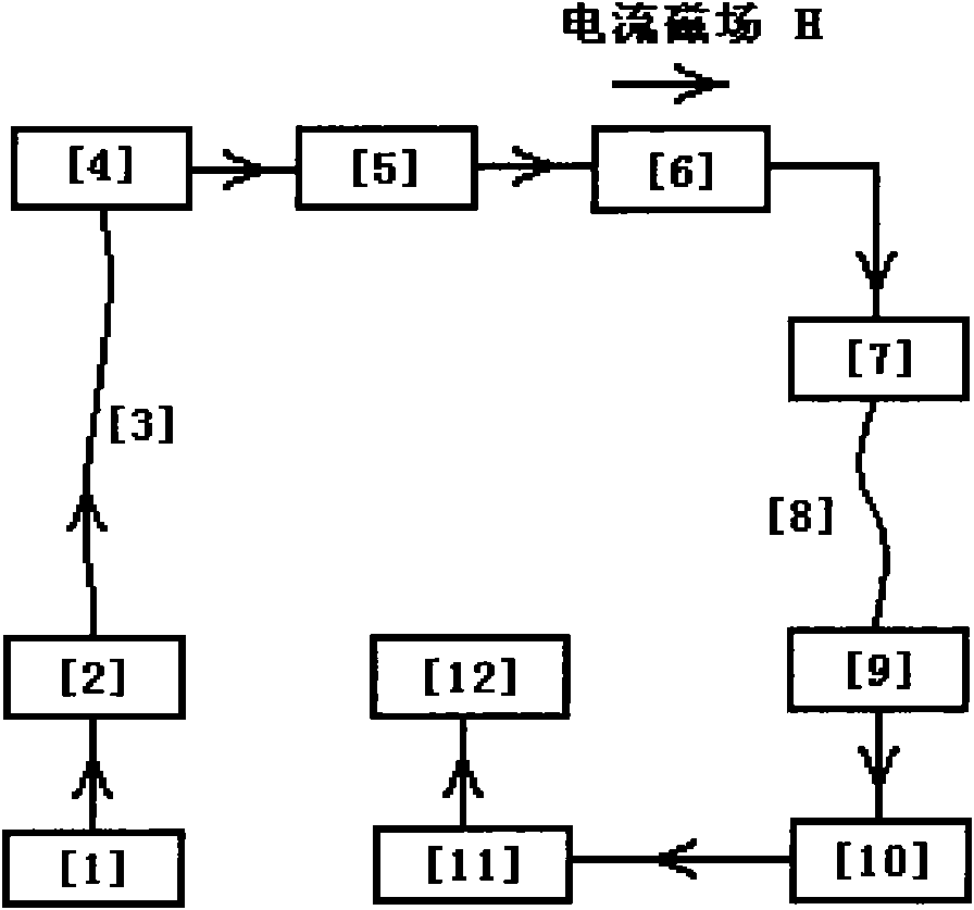
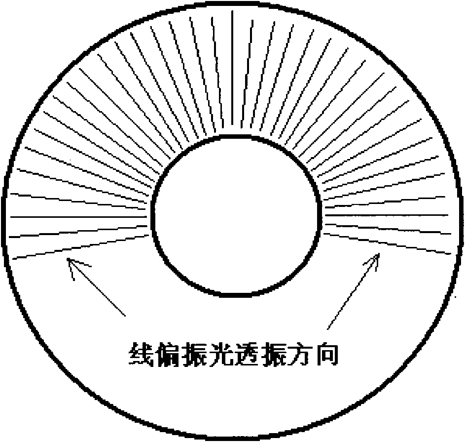
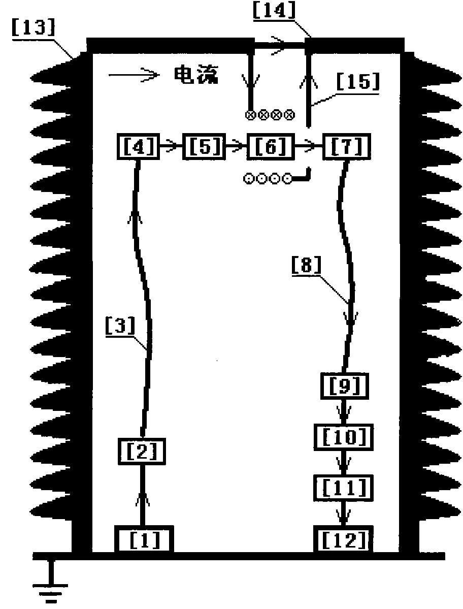
[0011] The specific implementation is as attached image 3 As shown, the laser signal [1] couples the optical signal to the transmission fiber [3] through the coupler [2] and transmits it from a low potential to a high potential, and is collimated by a collimator [4] and a polarizer [5] to obtain The linearly polarized light enters the magneto-optic crystal [6], the shunt solenoid [15] shunts the main wire current, and the magnetic field generated by the current flowing through [15] is consistent with the direction of the linearly polarized light and makes the polarization of the linearly polarized light The surface is rotated, and the linearly polarized light emitted from [6] is coupled to the transmission fiber [8] by the coupler [7] and transmitted to a low potential, collimated by the collimator [9] and expanded by the beam expander [10] Entering the circular analyzer [11], the light intensity distribution image formed by the polarized light passing through [11] is analyze...


PUM


Abstract

The invention relates to a digital optical fiber current sensor. The fundamental principle is that: based on a Faraday magnetic rotation effect, a polarization plane of linearly polarized light passing through a magneto-optical crystal can rotate under the action of the magnetic field of the current and the rotary angle is in direct proportion to the magnitude of the current. The polarization directions of an annular analyzer are distributed uniformly in a radial direction in a 180-degree annular region; the linearly polarized light consistent with a certain polarization direction on the annular analyzer can pass through the analyzer; the linearly polarized light vertical to the polarization direction cannot pass through the analyzer; and therefore, the intensity of the polarized light passing through the analyzer in a certain 90-degree region on the annular analyzer is decreased gradually from maximum to minimum, a light intensity distribution image is formed, the maximum or minimum light intensity position can be found through the analyzing process of a CMOS/CCD image sensor, the rotary angle of the polarized light is determined, and the real-time digital quantity of a current signal is acquired. A current measuring method is linear, so that the method is suitable for the measurement of alternating current and also can be suitable for the measurement of direct current.

Description

technical field [0001] The invention relates to a digital optical fiber current sensor. The basic principle is to rotate the polarization plane of linearly polarized light under the action of the current magnetic field based on the Faraday magnetic rotation effect, and to measure the rotation of the polarization plane by using a radial analyzer and a digital image processing method. Angle and get the digital current signal. It is suitable for AC and DC current measurement in power system. Background technique [0002] Current transformers or current sensors currently used in power systems are electromagnetic based on Faraday's electromagnetic induction principle and the analog magneto-optical type of magnetorotation effect and electronic type realized by Rogowski coils. [0003] The analog magneto-optical current sensor has a development history of more than 60 years. Its principle is based on the fact that the polarization plane of linearly polarized light rotates under th...

Claims


Application Information

Patent Timeline
IPC IPC(8): G01R19/25G01R15/24
Inventor 徐启峰
Owner FUZHOU UNIV
Why Eureka
Try Eureka