Magnetic rotation angle sensor
a technology of rotation angle and magnetic detection device, which is applied in the direction of galvano-magnetic devices, instruments, galvano-magnetic hall-effect devices, etc., can solve the problems of increasing the number of parts, raising manufacturing costs, and reducing the output level of magnetic detection devices
- Summary
- Abstract
- Description
- Claims
- Application Information
AI Technical Summary
Benefits of technology
Problems solved by technology
Method used
Image
Examples
first embodiment
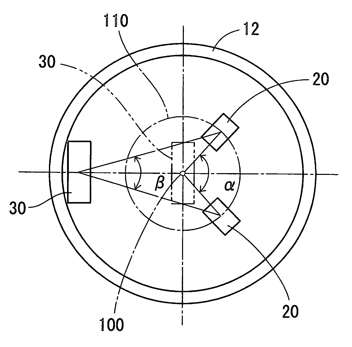
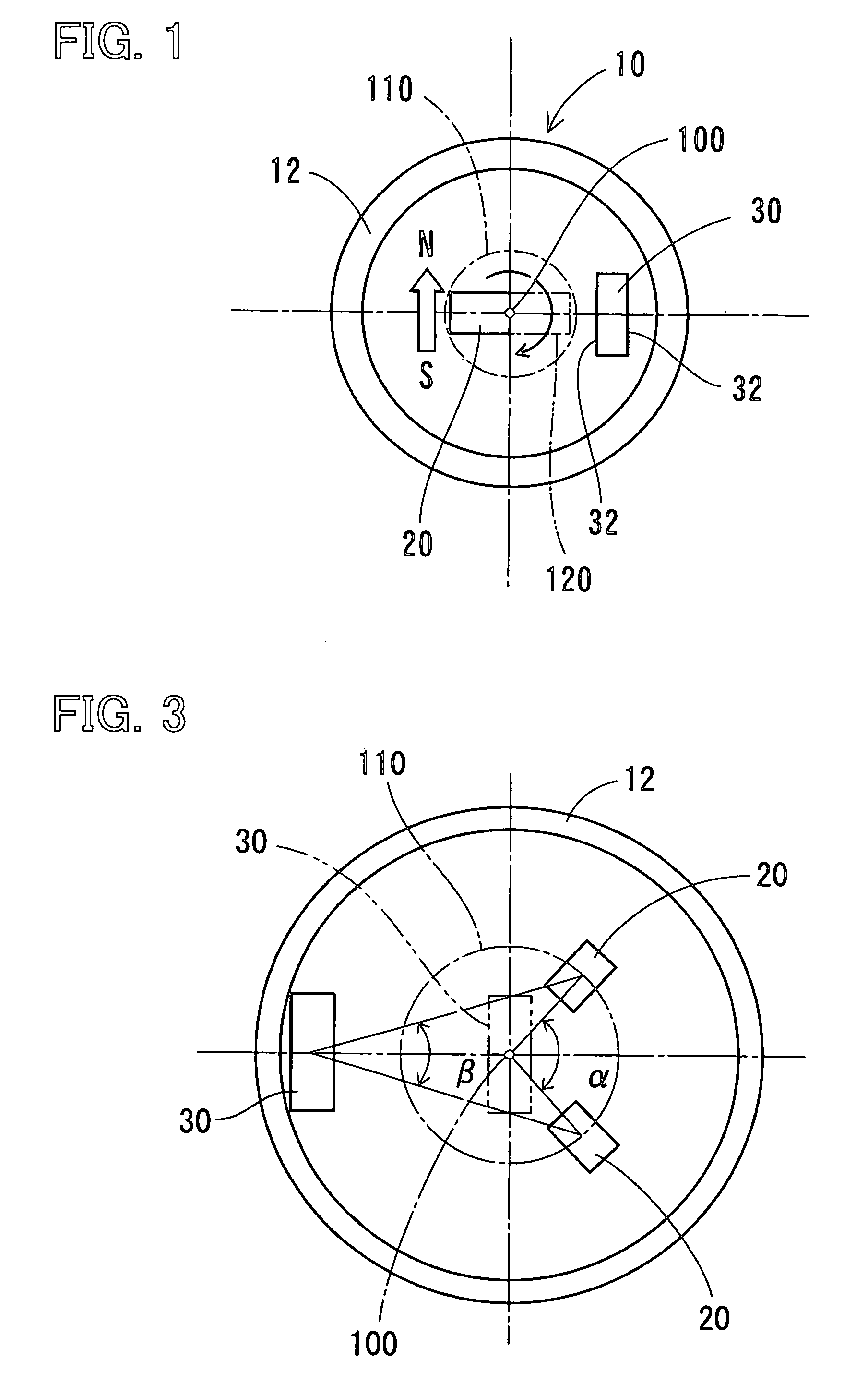
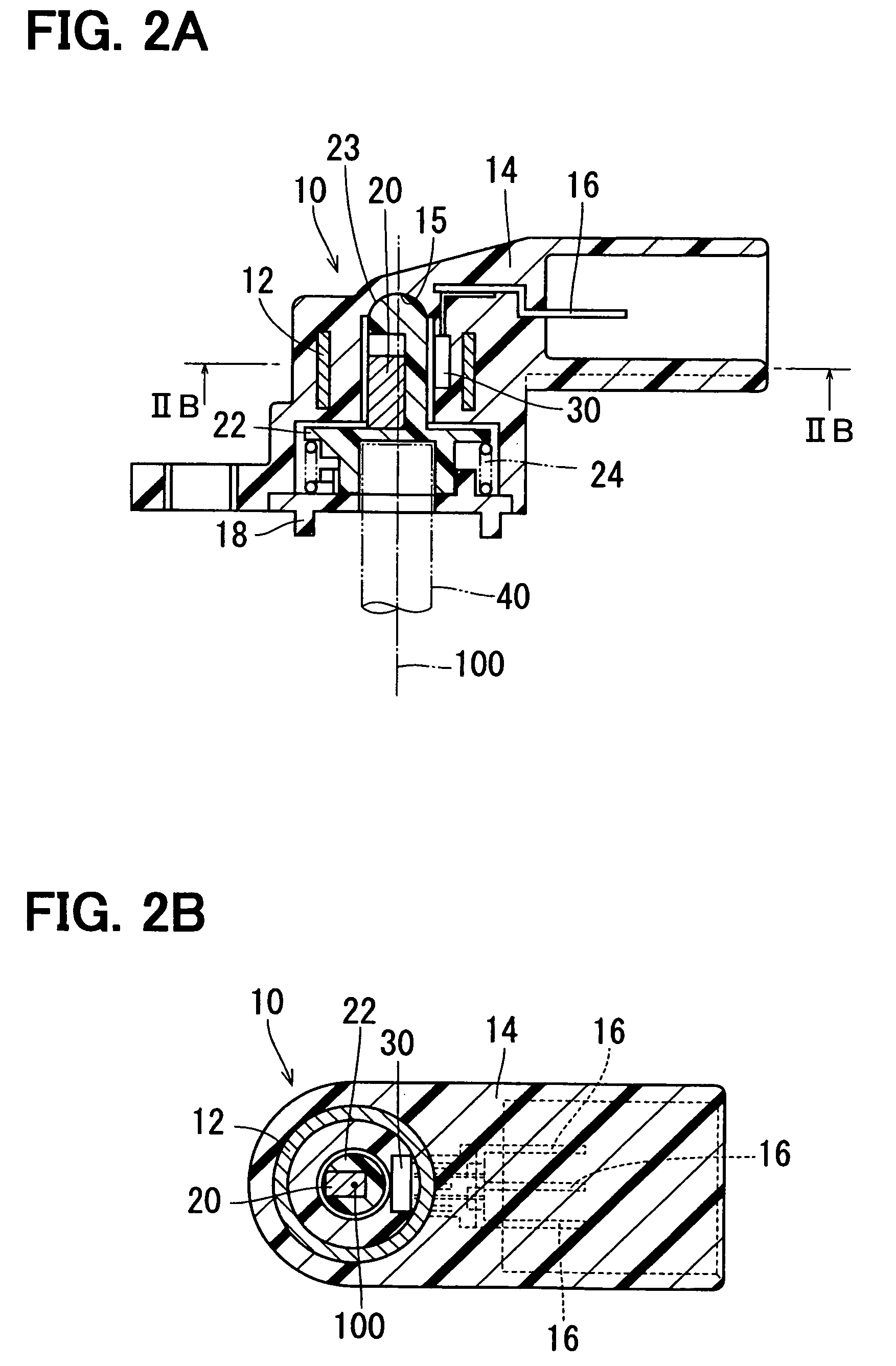
[0025]FIG. 1 depicts a magnetic rotation angle sensor 10 according to a first embodiment of the present invention. The magnetic rotation angle sensor 10 is a device for detecting a rotation angle of a detection target such as a throttle valve element. The magnetic rotation angle sensor 10 has a yoke 12, a magnet 20 and a Hall IC 30, which is an example of the magnetic flux density detection device according to the present invention. A Hall effect device may substitute for the Hall IC 30. The yoke 12 covers outer circumferences of the magnet 20 and the Hall IC 30.
[0026]The yoke 12 is formed from magnetic material into a cylindrical shape. The magnet 20 is a permanent magnet that rotates integrally with the detection target and is installed on a radially shifted position from a rotation center 100 of the detection target. The magnet 20 is magnetized along a turning circle of the detection target. The Hall IC 30 is installed on a radially shifted position from the rotational center 100...
second embodiment
[0053]FIG. 11 depicts an electromagnetic rotation angle sensor 50 according to a second embodiment of the present invention. In FIG. 11, components, to which the same referential numerals are assigned as in the first embodiment, are substantially the same as those in the first embodiment.
[0054]In the magnetic rotation angle sensor 50 according to the second embodiment, the magnet 20 is magnetized in a normal direction of the rotation path 110, which corresponds to the turning circle of the detection target. The detection surface 32 of the Hall IC 30 is in parallel to the normal direction of the rotation path 110. As in the first embodiment, the yoke 12 covers the outer circumferences of the magnet 20 and the Hall IC 30. Further, each of the magnet 20 and the Hall IC 30 is radially shifted from the rotation center 100. The magnet 20 is located on the inner circumferential side of the Hall IC 30.
[0055]By the above described magnetization direction of the magnet 20 and the arrangement ...
PUM
 Abstract
Description
Claims
Application Information
 - R&D
- Intellectual Property
- Life Sciences
- Materials
- Tech Scout
- Unparalleled Data Quality
- Higher Quality Content
- 60% Fewer Hallucinations
Browse by: Latest US Patents, China's latest patents, Technical Efficacy Thesaurus, Application Domain, Technology Topic, Popular Technical Reports.
© 2025 PatSnap. All rights reserved.Legal|Privacy policy|Modern Slavery Act Transparency Statement|Sitemap|About US| Contact US: help@patsnap.com


