
Magnetic rotation assembly capable of adjusting magnetic field and optical isolator

An optical component and magnet technology, applied in the field of lasers, can solve the problems of weakening magnetic field, rising cost, and increasing the distance between the upper and lower magnet components, etc., and achieves the effect of high magnetic field strength, cost saving, and guaranteed optical rotation angle.

Inactive Publication Date: 2015-09-09
MAXPHOTONICS CORP
View PDF6 Cites 11 Cited by
  • Summary
  • Abstract
  • Description
  • Claims
  • Application Information

AI Technical Summary

Problems solved by technology

However, this structure will increase the distance between the upper and lower magnet components due to the thickness of the Faraday crystal. At this time, the front and rear parts of the Faraday crystal cannot be surrounded by magnets, and the magnetic field is weakened.
In order to ensure the same optical rotation angle, it will be achieved by increasing the length of the Faraday device, which will greatly increase the cost
[0006] In summary, there are obviously inconveniences and defects in the actual use of the existing technology, so it is necessary to improve

Method used


Image

  • Magnetic rotation assembly capable of adjusting magnetic field and optical isolator
  • Magnetic rotation assembly capable of adjusting magnetic field and optical isolator
  • Magnetic rotation assembly capable of adjusting magnetic field and optical isolator

Examples


Embodiment Construction

[0031] In order to make the object, technical solution and advantages of the present invention clearer, the present invention will be further described in detail below in conjunction with the accompanying drawings and embodiments. It should be understood that the specific embodiments described here are only used to explain the present invention, not to limit the present invention.

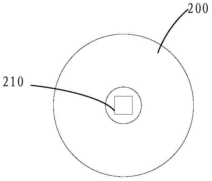
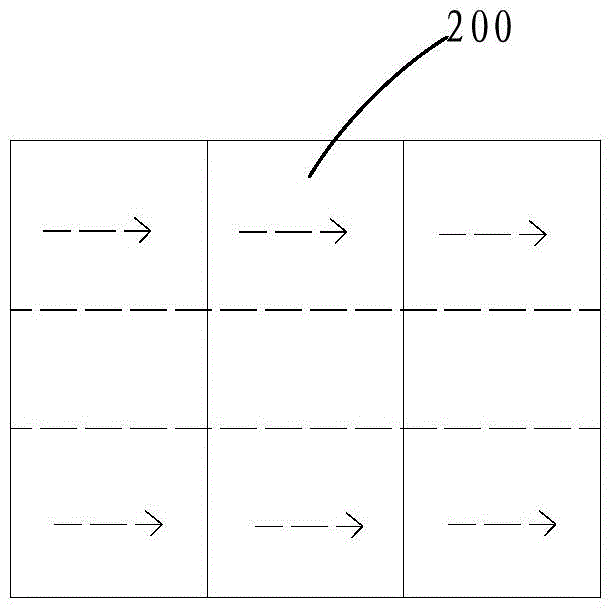
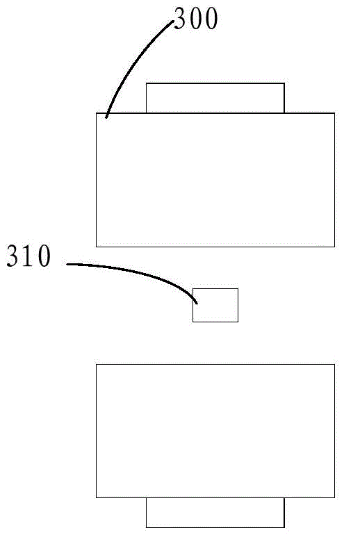
[0032] Combined with illustrations, such as Figure 3A , Figure 3B As shown, the present invention provides a magnet optical rotation assembly 100 with an adjustable magnetic field, including: at least one set of magnetic ring arrays, the magnetic ring array includes a first magnetic ring 10, a second magnetic ring 20 and a third magnetic ring 30, The first magnetic ring 10, the second magnetic ring 20 and the third magnetic ring 30 in the magnetic ring array are axially stacked and fixed, and at least one Faraday device 50 is arranged on the magnetic ring array in the central hole 60 and fixed;...


PUM


Abstract

The invention is suitable for the field of lasers and provides a magnetic rotation assembly capable of adjusting a magnetic field. The magnetic rotation assembly comprises at least one group of magnetic ring arrays. Each group of magnetic ring arrays comprises a first magnetic ring, a second magnetic ring and a third magnetic ring. The first magnetic ring, the second magnetic ring and the third magnetic ring of each group of magnetic ring arrays are stacked up in an axial direction and fixed. At least one Faraday device is arranged in a central hole of each magnetic ring array and fixed. The direction of a first magnetic line of each first magnetic ring is a radial direction pointing towards the outside from the center. The direction of a second magnetic line of each second magnetic ring points towards the axial direction from the left to the right. The direction of a third magnetic line of each third magnetic ring is a radial direction pointing towards the center from the outside. By adjusting axial distances or up-down distances among each first magnetic ring, each second magnetic ring and each third magnetic ring, an adjustment can be made to the magnetic field. The invention further discloses an optical isolator. Therefore, the magnetic rotation assembly capable of adjusting the magnetic field and the optical isolator helps to save cost and ensures ideal angle of rotation by making an adjustment to the magnetic field.

Description

technical field [0001] The invention relates to the field of lasers, in particular to a magnet optical rotation assembly and an optical isolator with an adjustable magnetic field. Background technique [0002] The isolator is an optical device suitable for the output of high-power lasers on a large scale, which effectively avoids the influence of the return beam on the laser beam processing surface. In the design of the isolator, a specific rotation angle is usually generated by combining a strong magnet with a Faraday device, so that the loss of the beam in the reverse direction is large, that is, high isolation. Here, the Faraday device is mainly used to rotate the light vector direction of the beam at a certain angle under a specific magnetic field. The following formula is usually used to characterize this characteristic: θ=VBL, where V is the Verdet constant, B is the magnetic induction, L is the length of the Faraday crystal, and θ is the light vector produced by the ...

Claims


Application Information

Patent Timeline
IPC IPC(8): G02F1/09
CPCH01F7/0273G02F1/09G02F1/093
Inventor 居剑张浩泰蒋峰
Owner MAXPHOTONICS CORP
Learn More