
Movable air conditioner and control method for removing condensation water

A kind of air conditioner, mobile technology, applied in the direction of control input related to system state, prevention of condensed water, space heating and ventilation control input, etc., can solve the problems of low condensed water discharge speed, artificial drainage treatment of water tanks, etc., to reduce The effect of operating power and enhancing heat exchange efficiency

Active Publication Date: 2005-01-05
HISENSE HOME APPLIANCES GRP CO LTD
View PDF0 Cites 25 Cited by
  • Summary
  • Abstract
  • Description
  • Claims
  • Application Information

AI Technical Summary

Problems solved by technology

This solution prolongs the full time of the water tank, but the discharge rate of condensed water is lower than the production rate under condensation conditions, and eventually there will still be a water tank full problem that requires manual drainage. The typical water full time is 2 to 4 hours

Method used


Image

  • Movable air conditioner and control method for removing condensation water
  • Movable air conditioner and control method for removing condensation water
  • Movable air conditioner and control method for removing condensation water

Examples


Embodiment 1

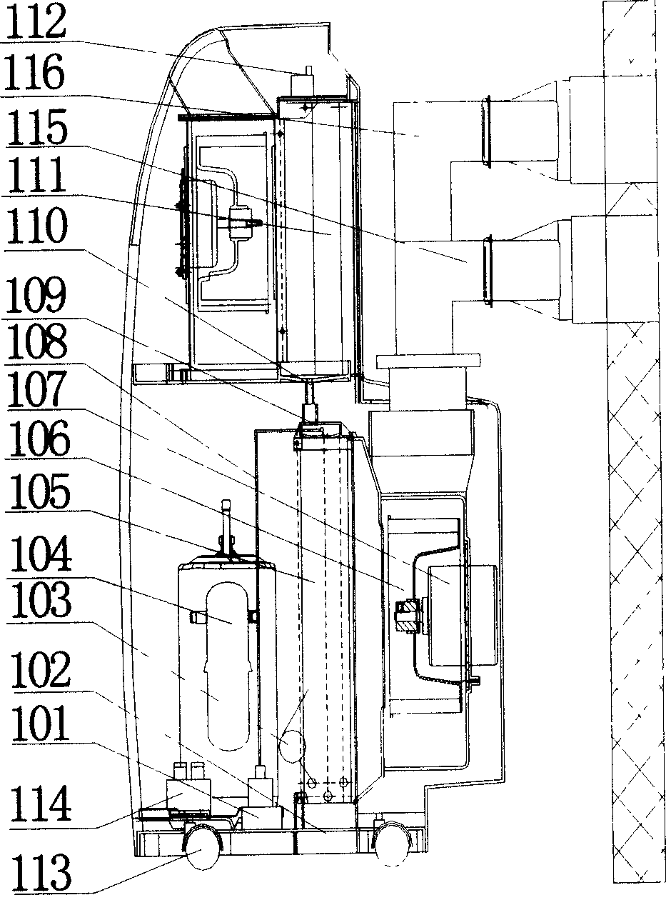
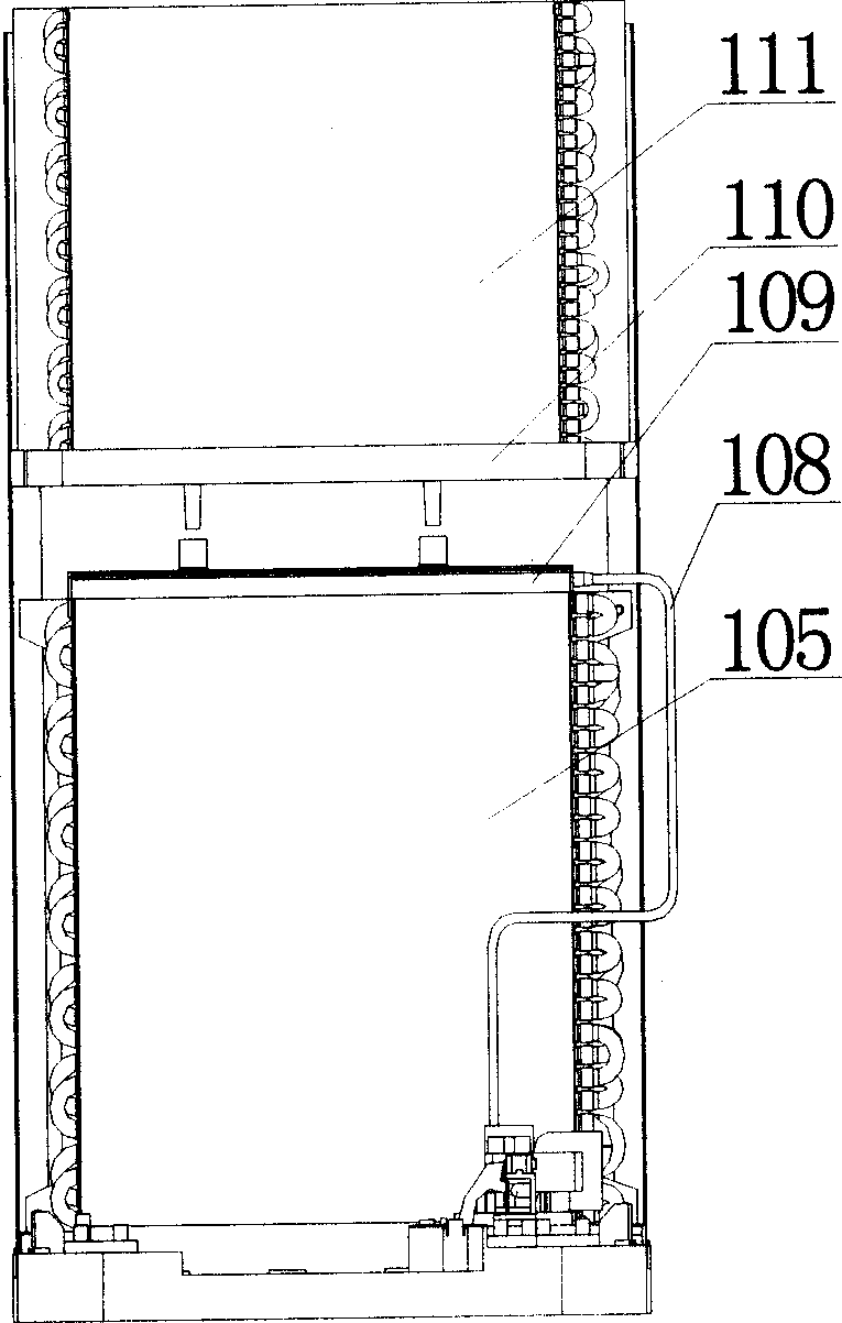
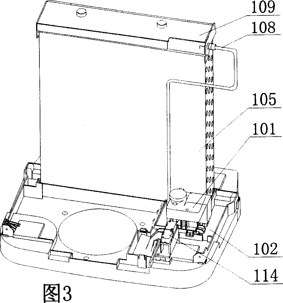
[0026] Such as figure 1 As shown, the present invention is a dual air duct mobile air conditioner that can be moved by casters 113 . The condenser 105 and evaporator 111 of the mobile air conditioner each use a motor that is independent of each other and controlled by the electric control device 112 . The compressor 104, the condenser 105, the throttling component 103, and the evaporator 111 are sequentially connected to form a refrigeration cycle system of the mobile air conditioner to provide cooling capacity for the system. The electric control device 112 is an electrical system, which effectively controls the safe, efficient and economical operation of the portable air conditioner. The spray box 109, the middle partition 110, the water tank 102, the water pump 101 for pumping the water in the water tank 102 to the condenser, the water level control device 114 for controlling the operation of the water pump, and the drain pipe 108 constitute the condensed water spraying sys...

Embodiment 2

[0030] As shown in FIG. 5 , the compressor 202 , the condenser 208 , the throttling component 201 , and the evaporator 214 constitute the refrigeration cycle system of the portable air conditioner to provide cooling capacity for the system. The electric control system 206 is an electrical system, which effectively controls the safe, efficient and economical operation of the portable air conditioner.

[0031] The condenser 208 and evaporator 214 of the portable air conditioner share the same motor and fan 207. After the indoor air is sucked into the portable air conditioner, it is distributed by the exhaust valve 209 and then enters the evaporator air separated by the partition plate 217. Road 212 and condenser air duct 210, one of which enters the evaporator air duct 212 to exchange heat with the evaporator 214 and then is sent to the room for cooling by the air outlet 215, and the other enters the condenser air duct 210 to exchange heat with the condenser 208 and then is disch...


PUM


Abstract

The invention relates to movable air conditioner and a control method for eliminating the condensed water, the mentioned movable air conditioner is made up of cooling system, spraying system and fan system. The cooling system is made up of a compressor, evaporator, restriction part and condenser. The spraying system includes a water box, the water in the box is transmitted to the pump of the condenser and the water level control device controlling the pump action, the fan system includes fan, motor for adjusting the rotational speed of the fan and the wind discharging pipe connected with the condenser. The invention also arranges an electric control device for controlling the wind quantity and the pump action. The control method adjusts the wind quantity of condenser, needs no additional work the condensed water can be eliminated. The invention not only solves the discharging problem of the condensed water, and increases the heat exchanging efficiency of the condenser through the condensed water spraying system.

Description

technical field [0001] The present invention relates to an air conditioner, in particular to a mobile air conditioner capable of removing condensed water without manual drainage. [0002] The present invention also relates to a control method for removing condensed water from the mobile air conditioner. Background technique [0003] When the mobile air conditioner is in cooling operation, if the surface temperature of the evaporator is lower than the indoor dew point temperature, condensed water will be generated on the evaporator. At present, the condensed water of mobile air conditioners on the market mainly adopts the following two methods: one is to directly use a water tank to collect the condensed water produced by the mobile air conditioner. Due to the limited volume of the water tank, when the water is full, frequent manual drainage is required to work normally. The typical water full time is 1 to 2 hours under condensation conditions, and ...

Claims


Application Information

Patent Timeline
Patent Type & Authority Applications(China)
IPC IPC(8): F24F1/04F24F13/22
CPCF24F13/222F24F2221/125F24F2013/225F24F2011/0054F24F2140/30
Inventor 黄晓峰李志军谈裕辉唐蔚陈绍安高祖裕
Owner HISENSE HOME APPLIANCES GRP CO LTD
Learn More