Linear light source of amplifying light focal length range

A linear light source, focal length technology, used in electroluminescent light sources, light sources, electric light sources, etc.

Active Publication Date: 2005-01-05
PIXON TECH CORP
View PDF0 Cites 6 Cited by
  • Summary
  • Abstract
  • Description
  • Claims
  • Application Information

AI Technical Summary

Problems solved by technology

Although it is relatively easy in the molding and injection process, it has inherent limitations in the control and effectiveness of l

Method used


Image

  • Linear light source of amplifying light focal length range
  • Linear light source of amplifying light focal length range
  • Linear light source of amplifying light focal length range

Examples


Embodiment Construction

[0023] In the following, specific embodiments are described in detail with reference to the accompanying drawings, so that it is easier to understand the purpose, technical content, features and effects of the present invention.

[0024] Although the basis of the present invention is based on the aforementioned Taiwan Patent No. 169467 and Application No. 92116083, further structural changes can not only improve the brightness and uniformity of the overall light output, but also improve the focal length range of the light. , in the application of image devices such as scanners, photocopiers, etc., it has better output effects.

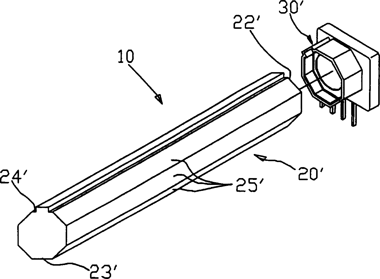
[0025] Firstly, the three-dimensional structure of the linear light source 1 of the present invention is shown in FIG. 4 , which mainly includes a light source assembly 10 , a light guide rod 20 and a reflective sleeve 30 covering the light guide rod. In order to clearly illustrate the structure of the present invention, please also refer to the explod...


PUM


Abstract

This invention is a linear illuminate which can increase the distinct range of its focus. It contains a guidance-light rod covered on it and a reflect-light cover tube. The light can be shoot from the rod's top; the face of the top has reflection function too. Any face of the whole rod has the reflection function. At the face of the shooting light the top has saw tooth which can advance gradually used to adjust index of reflection and refraction of the out light. The cover can mainly improve the reflection of the light and increase the brightness of the light. On the other side of the outlet of the rod, be designed a reflective plate coordinate with the design of gradually saw tooth reflective face, not only increase the brightness of the light and smoothly but also, maketto rod's light have wider range of its focus.

Description

technical field [0001] The invention relates to a linear light source, in particular to a device with a saw-toothed light guide rod and a reflective sleeve, which can improve the brightness and uniformity of the light and increase the clarity of the focal length of the light. Background technique [0002] By the way, scanners, fax machines, photocopiers and multi-functional peripheral business machines are frequently used in daily life and are common business machine equipment. These devices mainly use the optical principle to illuminate the target with a linear light source, and then sense the light and shade of the reflected light to obtain the output image. The quality of the output image has a lot to do with the scanning light source. The brightness of the emitted light is uniform. If the accuracy is not good, it will reduce the sensitivity and accuracy of the target object, making the output image effect not good. If the target object exceeds the focal length range (dep...

Claims


Application Information

Patent Timeline
IPC IPC(8): H05B33/22
Inventor 吴荣曜颜志明程士哲
Owner PIXON TECH CORP
Why Eureka
Try Eureka