Refrigerating valve

A technology for valves and valve stems, applied in the field of steel valves, which can solve the problems of easy leakage, disc wear, and impact on service life, and achieve the effects of avoiding severe wear, good sealing performance, and compact structure

Inactive Publication Date: 2005-01-12
许炎章
View PDF0 Cites 3 Cited by
  • Summary
  • Abstract
  • Description
  • Claims
  • Application Information

AI Technical Summary

Problems solved by technology

[0002] Valves are widely used in refrigeration, freezing, air conditioning, heat pump, chemical industry, petroleum and other industries. At present, most of the steel valves used for general refrigerants and non-corrosive gas and liquid control adopt traditional structure valves. Commonly used valves such as Globe valves, regulating globe valves, check valves, stop check valves, etc., due to their structure, there is a sliding sealing point between the valve stem and the valve body, which is difficult to solve the sealing problem of the refrigerant. Due to the manufacturing process, The valve stem may be eccentric. If the valve disc is not concentric with the valve body, it will affect the sealing performance of the valve when it is closed, and leakage will occur, and the valve disc will be severely worn by friction, which will affect the service life. Small and medium-sized valve seats are generally made of forged steel. structure, while the valve seat of larger size valves generally adopts steel pipe structure, and the connection between the valve seat and the pipeline adopts flange connection, which is prone to leakage

Method used


Image

  • Refrigerating valve
  • Refrigerating valve
  • Refrigerating valve

Examples


Embodiment Construction

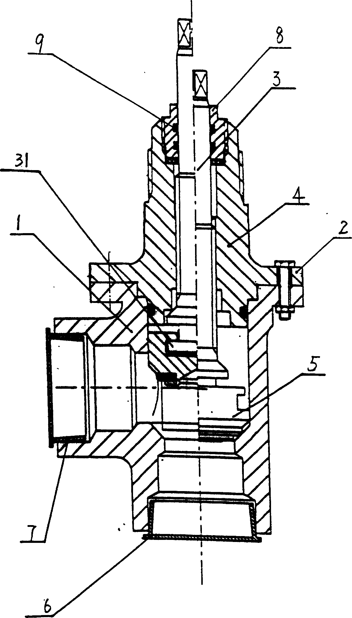
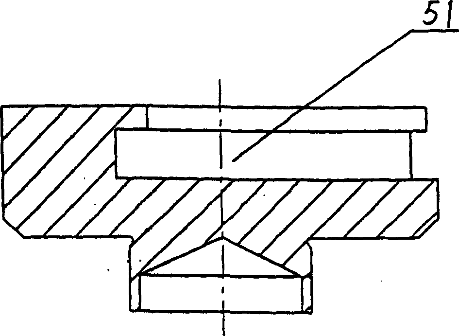
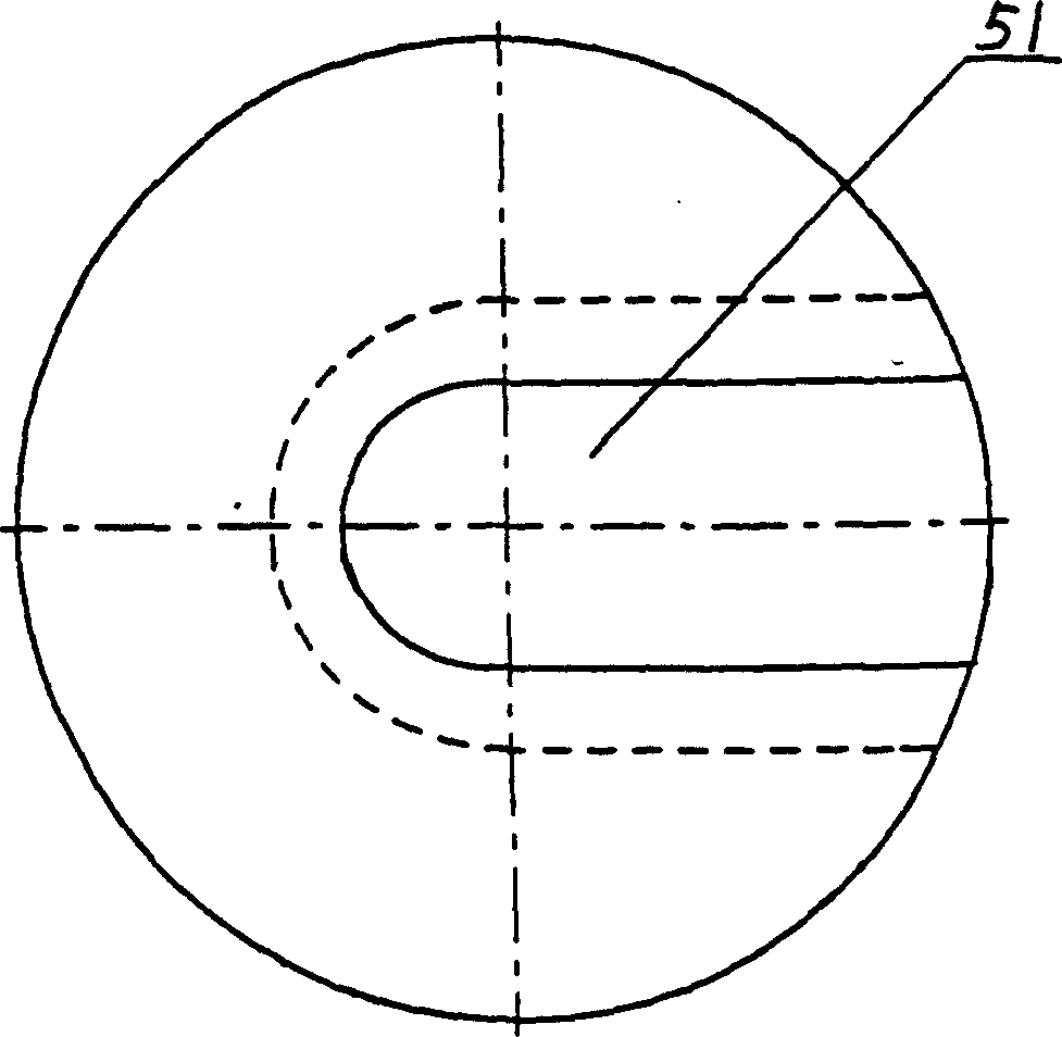
[0012] Such as figure 1 A refrigeration valve shown has a valve body 1, a valve cover 2, a valve stem 3, a valve stem sleeve 4, and a valve disc 5. The valve body 1 is provided with an inlet pipe 6 and an outlet pipe 7, and the valve stem sleeve 4 is arranged on On the valve cover 2 and connected with the valve cover 2, the valve disc 5 is arranged at the front end of the valve stem 3, the valve stem sleeve 4 is set on the valve stem 3, the valve stem 3 is threaded with the valve stem sleeve 4, and the valve stem 3 is connected with the valve stem sleeve 4. There is a sealing cover 8 between the valve stem sleeve 4, the sealing cover 8 is threadedly connected with the valve stem sleeve 4, the seal cover 8 and the valve stem sleeve 4 are sealed with a combined gasket, and the valve stem 3 and the sealing cover 8 are provided with double "O" Type ring or inverted "Y" ring 9 seal, valve body 1 and valve cover 2 are connected by bolts, valve cover 2 and valve body 1 are sealed wit...


PUM


Abstract

The valve is composed of the valve body, valve cap, valve shaft, valve petal and valve rod cover. The inlet and outlet pipes are fixed on the valve body. The valve rod cover is set on the cap. The valve petal is set at the front end of the shaft. The front end of the valve shaft and sealing ring are connected. The valve body is connected with the valve cap through the bolt and sealed by the '0' style sealing ring. The valve shaft is sealing connected with the valve petal, the cone interface forms the converse sealing. The sealing ring is settled between the sealing cap and valve rod cover, and between the valve shaft and valve cap.

Description

Technical field [0001] The present invention relates to a valve, especially a steel valve suitable for the control of all common refrigerants and non-corrosive gases and liquids. Background technique [0002] Valves are widely used in refrigeration, freezing, air conditioning, heat pump, chemical industry, petroleum and other industries. At present, most of the steel valves used for general refrigerants and non-corrosive gas and liquid control adopt traditional structure valves. Commonly used valves such as Globe valves, regulating globe valves, check valves, stop check valves, etc., due to their structure, there is a sliding sealing point between the valve stem and the valve body, which is difficult to solve the sealing problem of the refrigerant. Due to the manufacturing process, The valve stem may be eccentric. If the valve disc is not concentric with the valve body, it will affect the sealing performance of the valve when it is closed, and leakage will occur, and the val...

Claims


Application Information

Patent Timeline
Patent Type & Authority Applications(China)
IPC IPC(8): F16K1/02F16K1/36F16K1/48
Inventor 许炎章
Owner 许炎章
Why Eureka
Try Eureka