Locking device for dual capacity compressor

A latching device and compressor technology, which is applied to the components of the pumping device for elastic fluid, liquid variable capacity machinery, mechanical equipment, etc. Length, improved function, small friction coefficient

Inactive Publication Date: 2005-01-19
LG ELECTRONICS (TIANJIN) APPLIANCES CO LTD
View PDF1 Cites 6 Cited by
  • Summary
  • Abstract
  • Description
  • Claims
  • Application Information

AI Technical Summary

Benefits of technology

This new design for double-capacity compression machines has several benefits compared with previous designs such as improved lubrication efficiency or reduced wear caused by high pressure airflows during operation. It also allows for easy replacement of worn parts without having to disassemble any other components like an electric motor drive system. Overall, this technology improves performance and lifespan while reducing maintenance costs associated therewith

Problems solved by technology

The technical problem addressed in this patented technology relates to improving lubricant supply for both single or multiple valvellecage type scroll compressors during operation at low loads compared to larger capacities.

Method used


Image

  • Locking device for dual capacity compressor
  • Locking device for dual capacity compressor
  • Locking device for dual capacity compressor

Examples


Embodiment Construction

[0030] In order to further understand the content, characteristics and effects of the present invention, the following examples are given as examples and detailed descriptions are as follows in conjunction with the accompanying drawings:

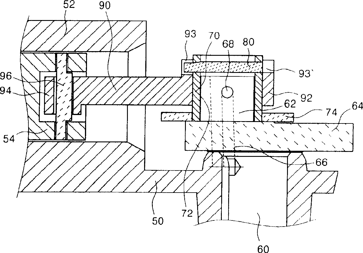
[0031] image 3 It is a cross-sectional view of the structure of the latch device of the double capacity compressor designed according to the present invention. As shown in the figure, a cylinder (52) is arranged on one side of the frame (50), and a piston (54) is arranged inside the cylinder (52), and the linear reciprocating motion of the piston is considered during setting. The frame (50) is located inside the airtight container of the compressor, and there are various other parts constituting the compressor inside.

[0032] The crankshaft (60) runs through the upper and lower sides of the frame (50). The crankshaft (60) is driven by the motor to rotate, and its upper end is provided with an eccentric portion (62). The eccentric portio...


PUM


Abstract

The invention is about a double capacity compressor. In the invention, a friction surface is formed between the periphery of the crankshaft eccentric part and the inside of the eccentric shaft sleeve. A through hole mounted with eccentric part is positioned on the eccentric shaft sleeve a little bit deflect from the center. on the top end of the eccentric shaft sleeve, a latch is arranged preventing the eccentric shaft sleeve rotating randomly. The latch must be mounted with one end convex to outside of the eccentric shaft sleeve. The eccentric shaft sleeve is placed on the center, on the eccentric part, the big port of the connecting lever is linked, and the big port must be kept rotatable. On the big port, a hook capable of hanging the latch is arranged. On bottom end of the eccentric shaft sleeve, a latch pendant is arranged. The invention can make the oil supply more smoothly and reduce the relative length of the connecting lever.

Description


Claims


Application Information

Patent Timeline
Owner LG ELECTRONICS (TIANJIN) APPLIANCES CO LTD
Why Eureka
Try Eureka