Package assembly for rotary type display unit

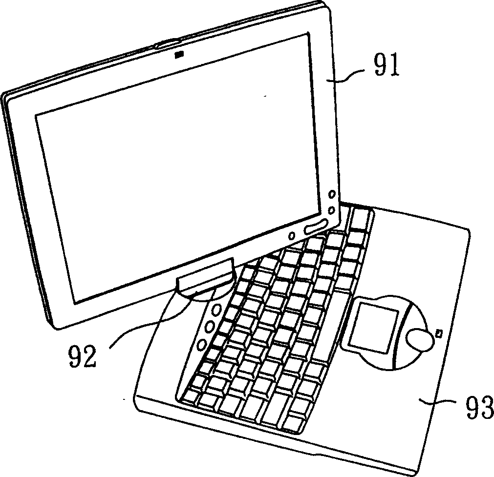
A technology for assembling structures and displays, applied in the direction of instruments, electrical digital data processing, digital data processing parts, etc., can solve the problems of the base 95 being incapable, losing elasticity, and reducing the life of the rotating disk 92, so as to strengthen the protection of the surrounding edges and improve elastic effect

Inactive Publication Date: 2005-01-19
TATUNG COMPANY
View PDF0 Cites 7 Cited by
  • Summary
  • Abstract
  • Description
  • Claims
  • Application Information

AI Technical Summary

Problems solved by technology

[0004] However, the above-mentioned rotating structure of the display relative to the rotation of the base still has disadvantages in use, please refer to figure 1 It is the display rotating structure of known dual-purpose portable computer, and it is that whole display 91 is pivotally connected on a rotating cone 92, and rotating disk 92 is then assembled on a base 93, therefore, display 91 can be relative to The rotating disc 92 is flipped up and down, and at the same time, the rotating disc 92 can rotate left and right relative to the base 93 to change the position of the display 91
However, the structure of the rotating disk 92 of this design is too complicated, and the rotating disk 92 is arranged at the bottom of the display 91. When the user applies force to the display 92 and makes it rotate, the parts in the rotating disk 92 It is very easy to cause damage due to uneven force, which relatively reduces the life of the rotating disk 92 and causes an increase in cost
[0005] see figure 2 It is another known display rotating structure of a dual-purpose portable computer. The display 94 and the base 95 are connected to each other by a special-style rotating shaft 96, that is, a relatively special corresponding structure must be used according to different styles of displays 94. The designed rotating shaft 96 will make the base 95 unable to be shared with different styles of displays 94, and lose its flexibility in assembly and production

Method used


Image

  • Package assembly for rotary type display unit
  • Package assembly for rotary type display unit
  • Package assembly for rotary type display unit

Examples


Embodiment Construction

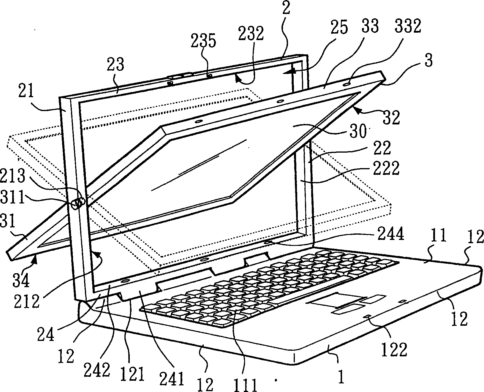
[0034] First, see image 3 It is a three-dimensional assembled view of the first preferred embodiment of the present invention, which shows a rotating display assembly structure, and the rotating display assembly structure mainly includes a base 1 , a hollow frame 2 , and a display 3 . The base 1 wherein includes an upper surface 11 and four side edges 12, and a keyboard set 111 is assembled on the upper surface 11, and in addition, a first pivot structure 121 is formed on one of the side edges 12. In an embodiment, the first pivot structure 121 is a pivot hole.

[0035] In addition, the hollow frame 2 in the drawing includes a left side 21, a right side 22, an upper side 23, and a lower side 24, and these left, right, upper and lower sides 21, 22, 23 , 24 and a hollow assembly area 25 is formed around it, and the left, right, upper and lower sides 21, 22, 23, 24 are respectively formed with an inner surface 212, 222, 232, 242 on the side corresponding to the hollow assembly ...


PUM


Abstract

The invention relates to a rotation display assembly structure, which is to group locate a hollow frame on the base socket and group locate a display in the hollow frame which can rotate relatively to the base socket and is covered on the base socket. The display can rotate in the hollow frame and to form a plane computer pattern for use or to form note computer pattern for use. Because the rotation element is located in the middle between the display and the hollow frame, the rotation element can be in force balance without damage when the display is bearing the force and starts rotation. Besides it can simplify structure design and lower cost and improve the process and assembly elasticity.

Description

technical field [0001] The invention relates to a rotating display assembly structure, especially a rotating display assembly structure suitable for a dual-purpose portable computer device. Background technique [0002] With the development of the information industry and the continuous advancement of related technologies, the current common computer devices have gradually derived many different types of products, such as desktop computers, notebook computers, tablet computers, etc. A dual-purpose portable computer that combines a notebook computer and a tablet computer. [0003] The above-mentioned dual-purpose portable computer mainly includes a base and a display, wherein the base is provided with a keyboard set, and the display can rotate relative to the base. When the display rotates and covers the base, the dual-purpose portable computer The computer can be used as a tablet computer, and when the display is rotated open, the dual-purpose portable computer can be used ...

Claims


Application Information

Patent Timeline
Patent Type & Authority Applications(China)
IPC IPC(8): G06F1/16
Inventor 赖自玮陈钦洲
Owner TATUNG COMPANY
Why Eureka
Try Eureka