
Coin slot for a mechanical coin-acceptor unit and mechanical coin-acceptor unit having a coin slot

A mechanical and detection machine technology, which is applied in the direction of coin inlet device, coin inspection, handling coins or valuable banknotes, etc., can solve the problems that hinder the normal function of the coin detection machine, and achieve the effect of accurate measurement

Inactive Publication Date: 2005-01-26
WALTER HANKE MECHANISCHE WERKSTATTEN
View PDF1 Cites 1 Cited by
  • Summary
  • Abstract
  • Description
  • Claims
  • Application Information

AI Technical Summary

Problems solved by technology

This prevents the coin detector from functioning properly

Method used


Image

  • Coin slot for a mechanical coin-acceptor unit and mechanical coin-acceptor unit having a coin slot
  • Coin slot for a mechanical coin-acceptor unit and mechanical coin-acceptor unit having a coin slot
  • Coin slot for a mechanical coin-acceptor unit and mechanical coin-acceptor unit having a coin slot

Examples


Embodiment Construction

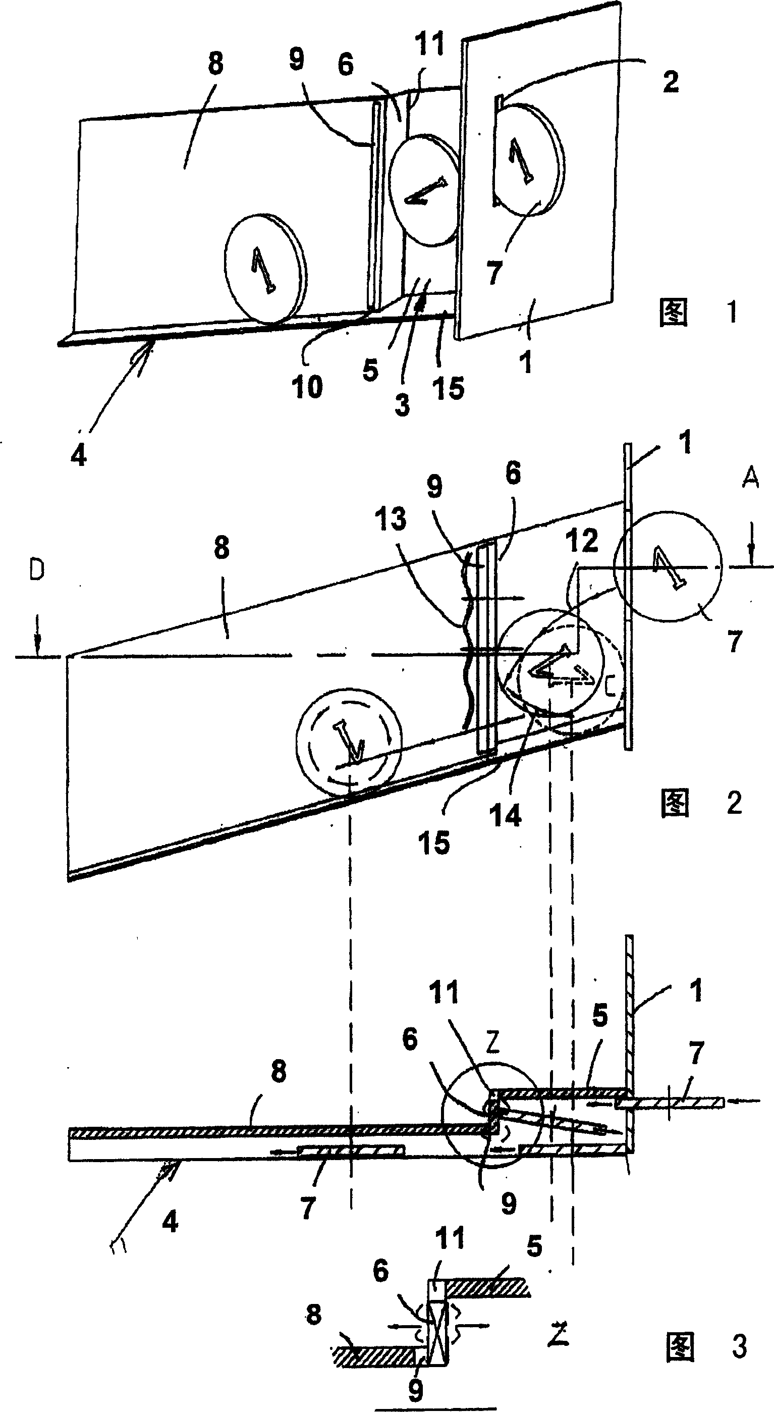
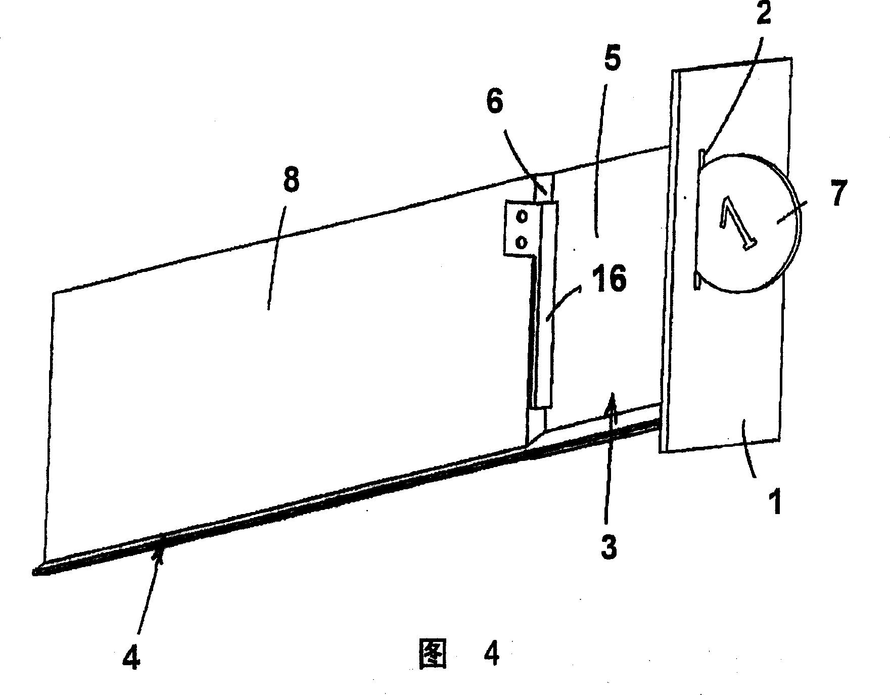
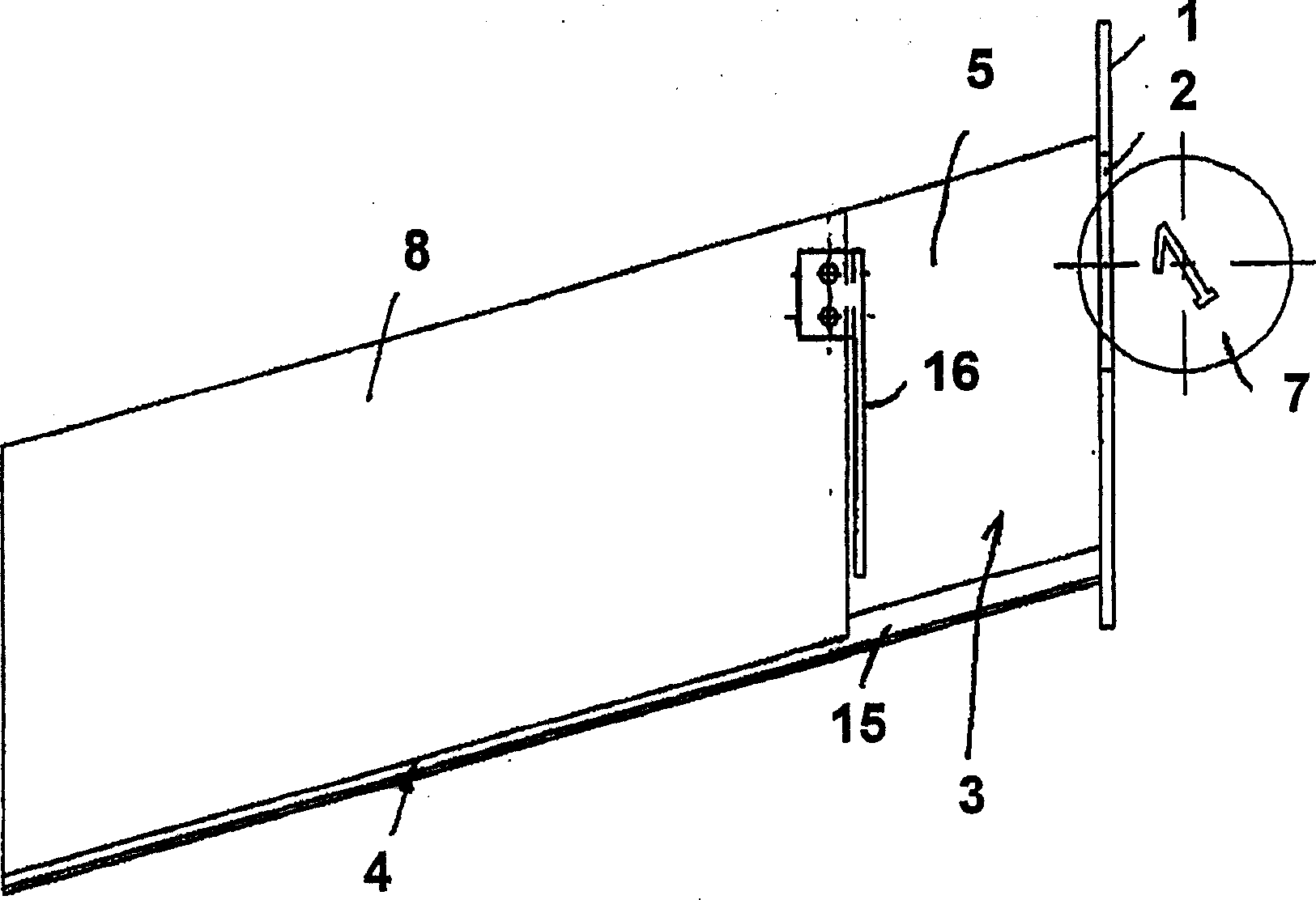
[0017] A base body 20 is fixed on a panel 1 and has a coin detection area 21 , a receiving area 22 connected thereto and a coin ejection area 23 . The base body 20 consists of multiple parts, including a base plate 24 with a clearance for the detection device, a cover plate 26 swingably mounted on the base plate 24 via a spring element 25, and a coin return slot 27 elastically fixed on the base plate , the coin return slot leads to a coin return port 28 on the panel 1 . A coin withdrawal button 29 is designed such that the cover plate 26 leaves the bottom plate 24 against the force of the spring element 25 so that inserted coins can drop into the coin withdrawal slot 27 .

[0018] The coin channel 4 or the coin running track that will be explained in detail below is slightly downwardly inclined, at Figure 6 Inclined to the left, it is defined on the one hand as a side wall 8 (see FIG. 1 ) by the base plate 24 and on the other hand by an upper rail 30 which has been partly re...


PUM


Abstract

The device has a coin insertion slot machined into a front panel (1), a coin insertion chamber (3), a coin channel (4) offset relative to the insertion slot and a shoulder (6) in the chamber after the slot in the insertion direction. The shoulder forms a coin reflector so that an incident coin (7) is elastically reflected by the shoulder towards the front panel and undergoes a new directional reversal in the chamber towards the coin channel. AN Independent claim is also included for the following: (a) a mechanical coin tester with an inventive coin input.

Description

technical field [0001] The invention relates to a coin input device of a mechanical coin detection machine and a mechanical coin detection machine with the coin input device. Background technique [0002] Mechanical coin detectors are well known, for example in US 4,545,474, a mechanical coin detector is fixed on a panel device. The coin detector has first and second coin running channels, and an opening between the two channels. In this known device, there is a boss or a baffle plate on the first coin running track. After the coin is thrown in, it rolls and hits the baffle plate along the running direction, then tilts to one side and continues to run on the first coin track. Coins may be guided through the opening onto a second coin-running track. Such a boss or step usually has an operation protection function, for example, so that it will not destroy the detection device of the mechanical coin detection machine when a wire or other tool is inserted into the coin slot. ...

Claims


Application Information

Patent Timeline
Patent Type & Authority Applications(China)
IPC IPC(8): G07F1/04
CPCG07F1/04Y10S193/01
Inventor C·特伦纳
Owner WALTER HANKE MECHANISCHE WERKSTATTEN
Learn More