Optical fiber, optical fiber module, and raman amplifier

A Raman amplifier, fiber module technology, applied in cladding fiber, optical waveguide light guide, optics, etc., can solve problems such as hindering high-speed optical communication and reducing the quality of signal optical communication.

Active Publication Date: 2005-02-02
FURUKAWA ELECTRIC CO LTD
View PDF0 Cites 0 Cited by
  • Summary
  • Abstract
  • Description
  • Claims
  • Application Information

AI Technical Summary

Problems solved by technology

[0003] However, although this existing optical fiber obtains an amplification of more than 20dB with an excitation light of about 500mW, it also produces a large nonlinear phase shift at the same time, and there is a problem that the communication quality decreases due to the deterioration of the waveform of the signal light, which hinders high-speed optical communication. a major factor of

Method used


Image

  • Optical fiber, optical fiber module, and raman amplifier
  • Optical fiber, optical fiber module, and raman amplifier
  • Optical fiber, optical fiber module, and raman amplifier

Examples


Embodiment Construction

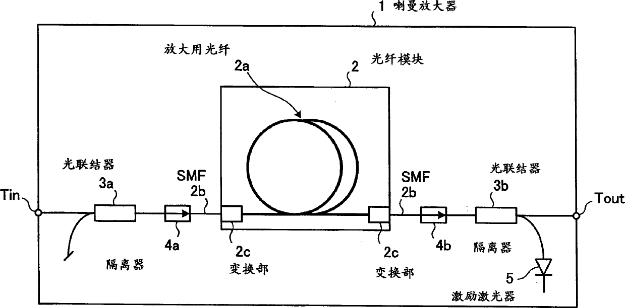
[0024] Embodiments of the present invention will be described below with reference to the drawings. Fig. 1 is a block diagram showing the structure of a Raman amplifier of an embodiment of the present invention. This Raman amplifier 1 is a centralized Raman amplifier and has an optical fiber module 2 . The signal optical input terminal Tin is connected to the optical fiber module 2 through the optical connector 3a and the isolator 4a. The optical fiber module 2 connects the amplified signal light to the output terminal Tout through the isolator 4b and the optical connector 3b. The optical connector 3 b is connected to the excitation laser 5 , and outputs the excitation light from the excitation laser 5 to the side of the optical fiber module 2 .

[0025] The optical fiber module 2 has an amplifying optical fiber 2a, which will be described later, wound on a bobbin, and between the single-mode optical fiber (SMF) optical fiber 2b on the side of each isolator 4a, 4b and the am...


PUM

PropertyMeasurementUnit
Diameteraaaaaaaaaa

Abstract

An optical fiber has a Raman gain efficiency with a pump power at 1450 nanometers of equal to or more than 4 m / W, and a ratio of a nonlinear parameter gamma at a wavelength of 1550 nanometers to the Raman gain efficiency with a pump power of 1450 nanometers is equal to or less than 3.

Description

technical field [0001] The invention relates to an optical fiber, an optical fiber module and a Raman amplifier suitable for high-speed optical communication. Background technique [0002] In recent years, a Raman amplifier can amplify in a desired wavelength bandwidth, and has attracted attention as an amplifier capable of achieving gain also in a wide wavelength region of 100 nm. The optical fiber used in the amplifying medium of this Raman amplifier is a quartz matrix, which is applicable to any optical fiber, but as a concentrated Raman amplifier, the Raman gain efficiency (GR / Aeff=Raman gain coefficient / effective Core cross-sectional area) 6.5 or more optical fiber, using about 500mW excitation light to obtain a gain of more than 20dB. [0003] However, although this existing optical fiber obtains an amplification of more than 20dB with an excitation light of about 500mW, it also produces a large nonlinear phase shift at the same time, and there is a problem that the c...

Claims


Application Information

Patent Timeline
IPC IPC(8): G02B6/02G02F1/35G02F1/39
Inventor 杉崎隆一谷口友规八木健
Owner FURUKAWA ELECTRIC CO LTD
Why Eureka
Try Eureka