Elevator system

An elevator system and elevator technology, used in elevators, transportation and packaging, etc., can solve problems such as collisions and program failures, and achieve the effect of saving floor space, saving space, and good income

Inactive Publication Date: 2005-02-09
KONE CORP
View PDF2 Cites 2 Cited by
  • Summary
  • Abstract
  • Description
  • Claims
  • Application Information

AI Technical Summary

Problems solved by technology

The problem here is also the risk of collision, since there is always the possibility that if the program malfunctions or an error occurs, two cars moving towards each other in the same shaft will collide

Method used


Image

  • Elevator system
  • Elevator system
  • Elevator system

Examples


Embodiment Construction

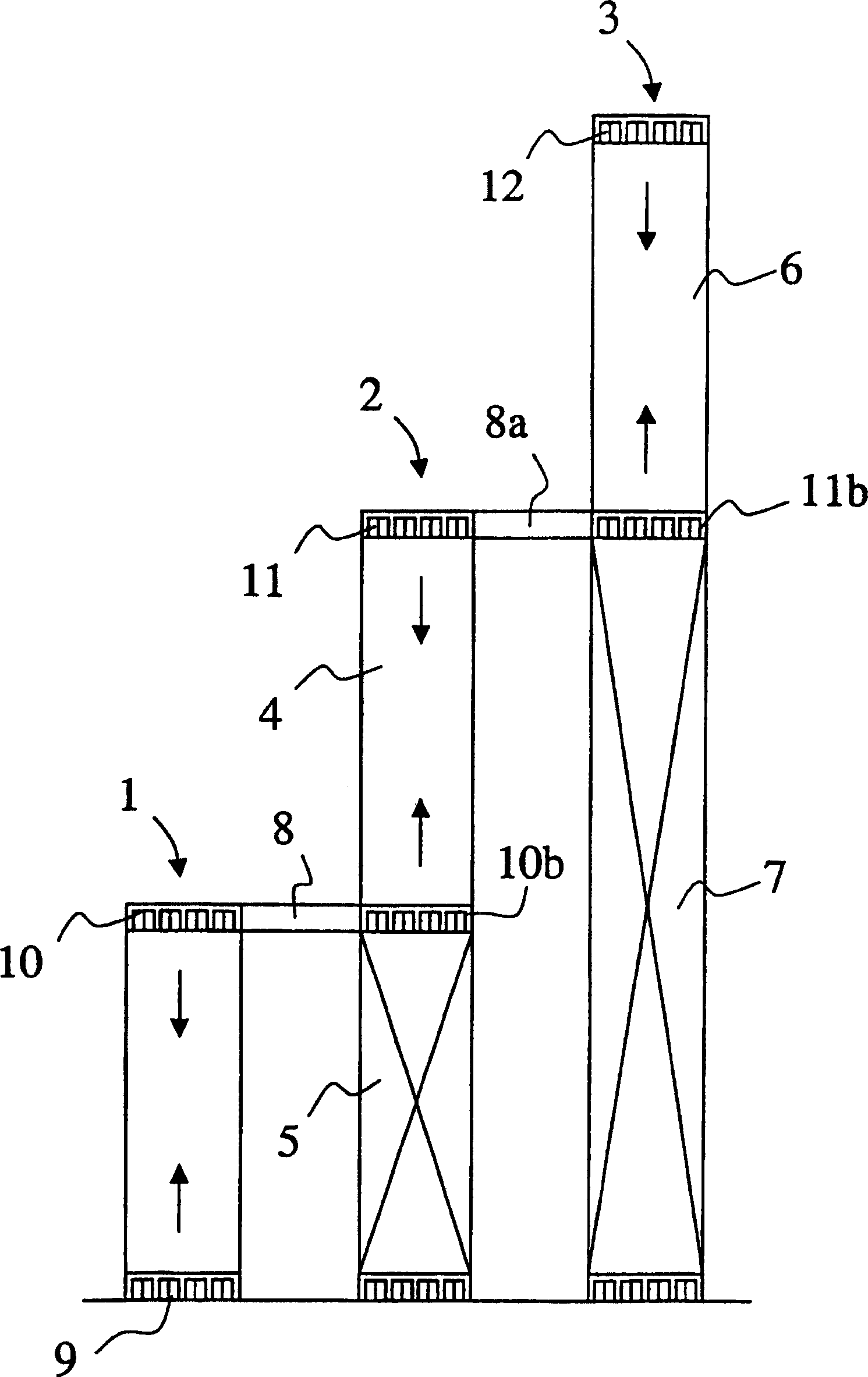
[0015] figure 1 The shown solution is representative of the existing elevator system for high-rise buildings described above. We assume that the building has 45 floors, and every 15 floors is an area. The number of floors in each zone is determined by the number of elevators, car size and elevator speed. The system comprises three zones of different heights, thus requiring three different sets of elevator shafts 1, 2 and 3, with set 1 forming the lowest zone comprising a set of, for example, 8 elevators, from the ground floor 9 to the highest floor of the zone. All 15 lowest floors of 10 serve, figure 1 Only the elevator doors of the 4 elevators at the ground floor 9 and the highest floor 10 of the area are shown. In this area, the elevator can stop at any floor.

[0016] The second area of ​​the existing elevator system is the so-called intermediate area, which may also comprise a group of 8 elevator groups in a separate elevator shaft group 2, which only serves the groun...


PUM


Abstract

The invention relates to an elevator system in tall buildings, said system comprising at least one first elevator shaft (13), which houses an elevator arranged to stop at floors called transfer levels (8, 8a), and at least one second elevator shaft (14), which houses elevators whose elevator cars (22) are disposed one above the other in the elevator shaft, which elevator cars are designed to stop during their travel at any floor to which or from which a call has been issued. The second elevator shaft (14) is divided vertically into local shafts (17, 18, 19) situated one above the other, the number of which is at least one for each zone between transfer levels (8, 8a).

Description

technical field [0001] The invention relates to an elevator system as defined in the preamble of claim 1, and in particular to an elevator system for high-rise buildings in which passengers wishing to reach the upper floors have to change to an elevator mainly serving only the upper floors . Background technique [0002] In very tall buildings it is generally not economical to provide a shaft extending the entire height from the ground floor to the top floor so that each elevator serves all floors. For this reason, elevators are usually divided into different areas in the vertical direction, wherein the lowest area extends from the entrance floor, that is, the ground floor, to a designated level, which is called the low floor area, and the upper area, called the upper floor area, extends from the so-called high floor area. The designated transfer level at the upper porch level extends to the topmost level of the building. Between these areas, depending on the height of the...

Claims


Application Information

Patent Timeline
Patent Type & Authority Applications(China)
IPC IPC(8): B66B1/00B66B1/18
CPCB66B1/18
Inventor 西莫·乔凯拉里塔·帕塔南-乔凯拉约翰尼斯·德琼
Owner KONE CORP
Why Eureka
Try Eureka