Lens shift mechanism and projection type video display

A lens movement and image technology, applied in projection devices, printing devices, installations, etc., can solve the problems of reducing the amount of projected light, offset, etc.

Active Publication Date: 2005-02-16
SANYO ELECTRIC CO LTD
View PDF1 Cites 9 Cited by
  • Summary
  • Abstract
  • Description
  • Claims
  • Application Information

AI Technical Summary

Problems solved by technology

[0003] In the lens shift mechanism, a relatively large lens shift range can be ensured in the vertical direction or the left and right direction, but when the projection lens is moved largely according to such a large lens shift range, there will be a large difference between the optical axis of the projected image and the optical axis of the projection lens. offset, which leads to the problem of reducing the amount of projected light

Method used


Image

  • Lens shift mechanism and projection type video display
  • Lens shift mechanism and projection type video display
  • Lens shift mechanism and projection type video display

Examples


Embodiment Construction

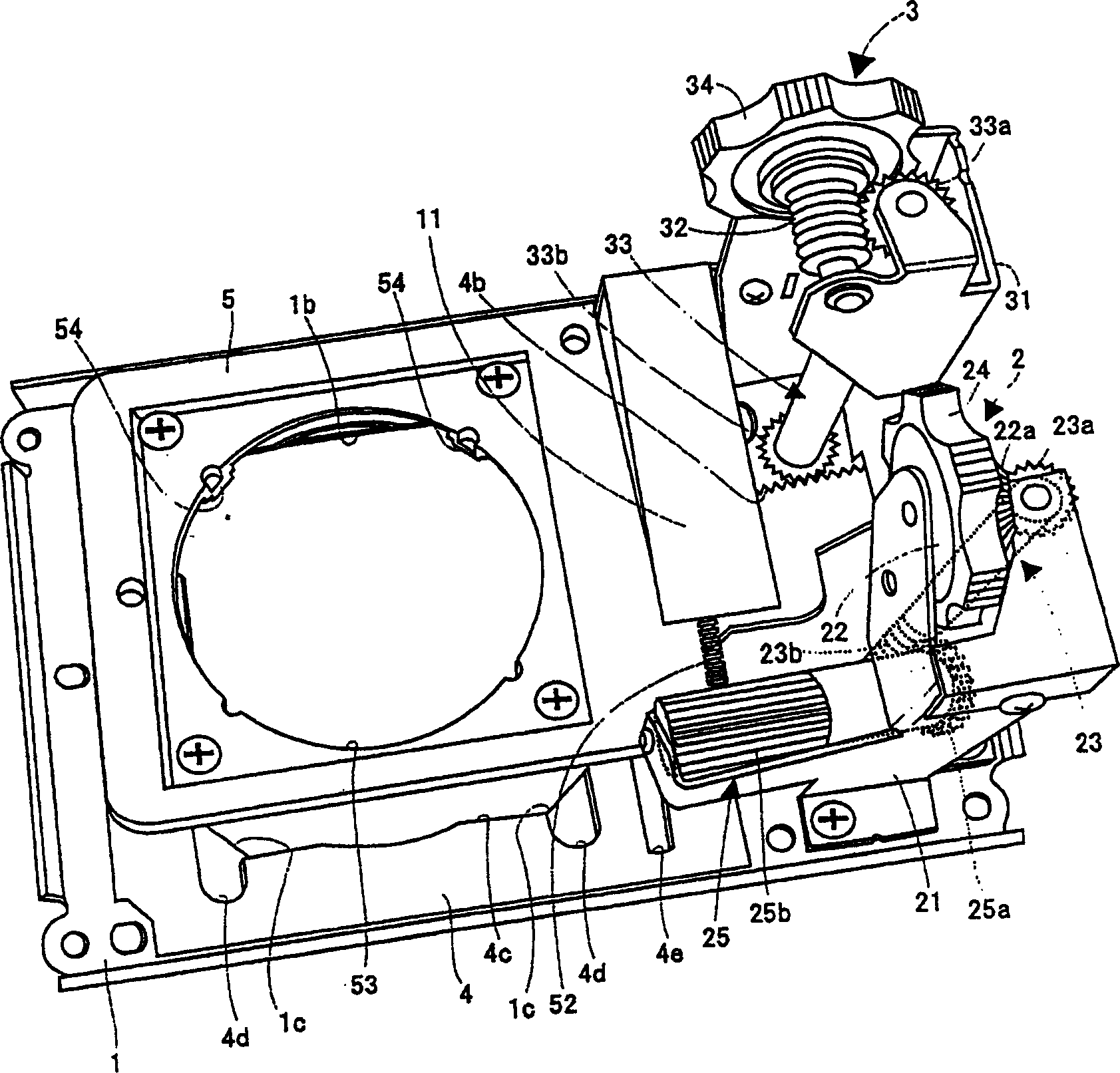
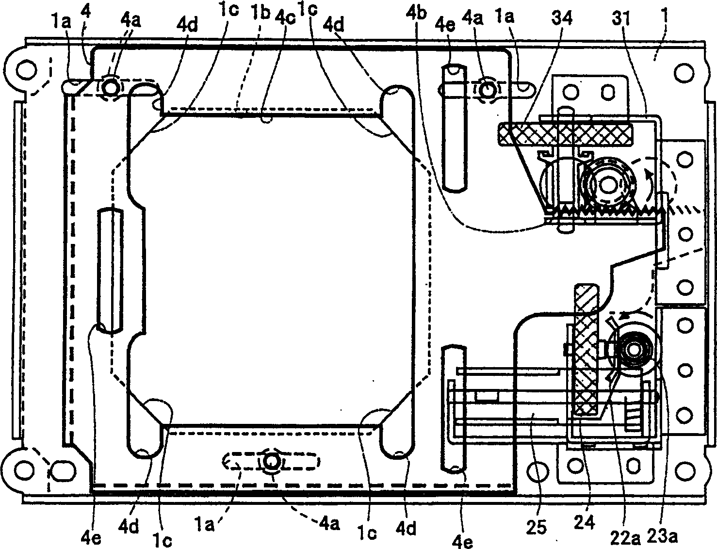
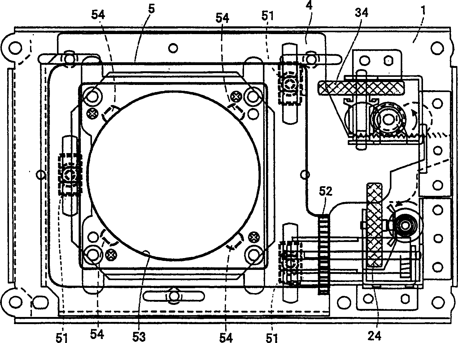
[0016] Below, refer to Figure 1 ~ Figure 4 A lens shift mechanism and a projection type image display device according to an embodiment of the present invention will be described. First, an example of the optical system of the liquid crystal projector is shown. Figure 4 It is a diagram showing the optical system of the 3-panel color liquid crystal projector. The light emitting part of the light source 101 is composed of an ultra-high pressure mercury lamp, a metal halide lamp, a xenon lamp, etc., and uses a parabolic reflector to convert the irradiated light into parallel light and emit it, and then guide it to the integrator lens 102 .

[0017] The integrating lens 102 is composed of a pair of lens groups, and each lens pair guides light emitted from the light source 101 to the entire surfaces of the liquid crystal light valves 111 , 112 , and 113 . The light passing through the integrating lens 102 is guided to the first dichroic mirror 103 .

[0018] The first dichroic...


PUM


Abstract

When an attempt to move a projection lens in a horizontal direction (crosswise) in a state where it is positioned on the upper or lower side is made, it can be moved in the horizontal direction (crosswise) up to a certain range. However, a movement restraining convex area in a vertical movable base finally comes into contact with the corner inclined at an angle of 45 degrees in a fixed base. After this contact, movement in a leftward or rightward direction and an upward or downward direction which are limited directions is limited. Even if a dial and a dial are rotated in the limited directions under the limitation of the movement, they are slipped, thereby making it possible to prevent a force from being forcedly applied to a driving mechanism.

Description

technical field [0001] The invention relates to a lens moving mechanism and a projection type image display device. Background technique [0002] It is well known that such a liquid crystal projector is provided with a lens shift mechanism for moving the projected image up and down while keeping the main body intact, or reducing the projected image to form a trapezoidal shape (JP-A-9-138377). [0003] In the lens shift mechanism, a relatively large lens shift range can be ensured in the vertical direction or the left and right direction, but when the projection lens is moved by such a large lens shift range, the optical axis of the projected image and the optical axis of the projection lens will have a large discrepancy. offset, which leads to the problem of reducing the amount of projected light. Contents of the invention [0004] The present invention was developed in view of the above circumstances, and an object of the present invention is to provide a lens moving mec...

Claims


Application Information

Patent Timeline
Patent Type & Authority Applications(China)
IPC IPC(8): G02F1/13G02B7/02G02F1/1335G03B5/06G03B21/14
CPCG02B7/023
Inventor 义之宏充
Owner SANYO ELECTRIC CO LTD
Why Eureka
Try Eureka