Air conditioner

A technology for air conditioners and compressors, which is applied in the direction of refrigerators, compressors, and machine operation methods. It can solve problems such as wasting electricity, and achieve the effects of avoiding unnecessary waste, reducing power consumption, and improving reliability.

Inactive Publication Date: 2005-03-09
PANASONIC CORP
View PDF1 Cites 26 Cited by
  • Summary
  • Abstract
  • Description
  • Claims
  • Application Information

AI Technical Summary

Problems solved by technology

[0004] However, in the conventional air conditioner having the above structure, in order to maintain the switch device in the normally closed state during the rehea

Method used


Image

  • Air conditioner
  • Air conditioner

Examples


Embodiment Construction

[0015] Next, specific embodiments of the present invention will be described with reference to the drawings. Moreover, this embodiment is not limited to this invention.

[0016] Refer below figure 1 as well as figure 2 Preferred embodiments of the present invention will be described.

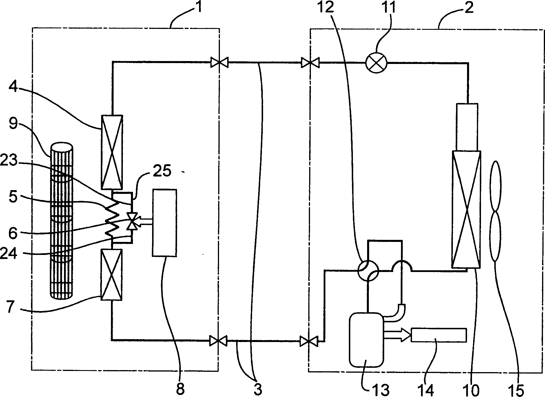
[0017] figure 1 The air conditioner in this embodiment is composed of an indoor unit 1 installed indoors, and an outdoor unit arranged outdoors and connected to the indoor unit 1 via a heat medium circulation circuit 3 .

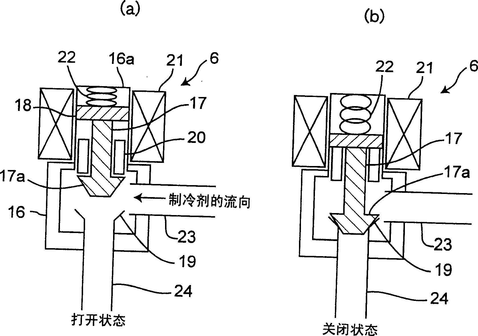
[0018] The indoor unit 1 is built with a first indoor heat exchanger 4 and a second indoor exchanger 7 connected in series with the first indoor exchanger 4 via a throttling device 5 . Between the indoor heat exchanger 4 and the second indoor heat exchanger 7, a bypass passage 25 connected in parallel with the throttling device 5, and an indoor fan 9 with adjustable air volume. The bypass passage 25 is composed of an electric normally open solenoid valve 6, a first refri...


PUM


Abstract

An indoor heat exchanger is structured with a first indoor heat exchanger and a second indoor heat exchanger serially connected to the first indoor heat exchanger via a diaphragm means. A bypass route, parallely connected to the diaphragm means, having the open/close means of an always-open type. When starting a re-heat-dehumidifying operation which operates the first indoor heat exchanger as a condenser and operates the second heat exchanger as an evaporator, electric power is supplied to the open/close means to close and, after electric power supply is stopped, high refrigerant pressure is applied to a valve element and a status in which a valve seat is closed by the valve element is maintained. Thus, it can provide an air conditioner of which power consumption to activate an open/close means is small.

Description

technical field [0001] The invention relates to an air conditioner, in particular to a control on an on-off valve during reheating and dehumidification operation. Background technique [0002] Regarding conventional air conditioners capable of reheating and dehumidifying operation, the indoor heat exchanger is composed of a first indoor heat exchanger and a second indoor heat exchanger connected in series through a throttling device. A bypass passage with a solenoid valve is connected between the second indoor heat exchanger and the throttling device, and the switch of the on-off valve is controlled by the control device. [0003] Then, during the reheating and dehumidification operation, the on-off valve is always energized and the on-off valve is closed, the first indoor heat exchanger functions as a condenser, and the second indoor heat exchanger functions as an evaporator (for example, refer to Japanese Patent No. Publication No. 2002-106913). [0004] However, in the ...

Claims


Application Information

Patent Timeline
IPC IPC(8): F24F11/02F25B1/00F25B29/00F25B41/04
Inventor 平谷寿士十仓聪新田武彦
Owner PANASONIC CORP
Why Eureka
Try Eureka