
Thread ram means of sewing machine

A sewing machine and thread take-up technology, applied in the field of thread take-up devices, can solve the problems of complicated movement, changing the sewing style, and inability to obtain finished products, etc.

Inactive Publication Date: 2010-04-28
BROTHER KOGYO KK
View PDF3 Cites 2 Cited by
  • Summary
  • Abstract
  • Description
  • Claims
  • Application Information

AI Technical Summary

Problems solved by technology

[0007] Therefore, the sewing style cannot be easily changed as expected, and there is a problem that the finished product of the desired style cannot be obtained.
Also, since a pair of cam thread catchers are separately formed on both sides of the upper thread cam, and are respectively fixed by screws, when adjusting the phase of the thread take-up curve, it is necessary to carry out a movement equal to that of these cam thread catchers. The mobile operation will make the mobile complicated and troublesome

Method used


Image

  • Thread ram means of sewing machine
  • Thread ram means of sewing machine
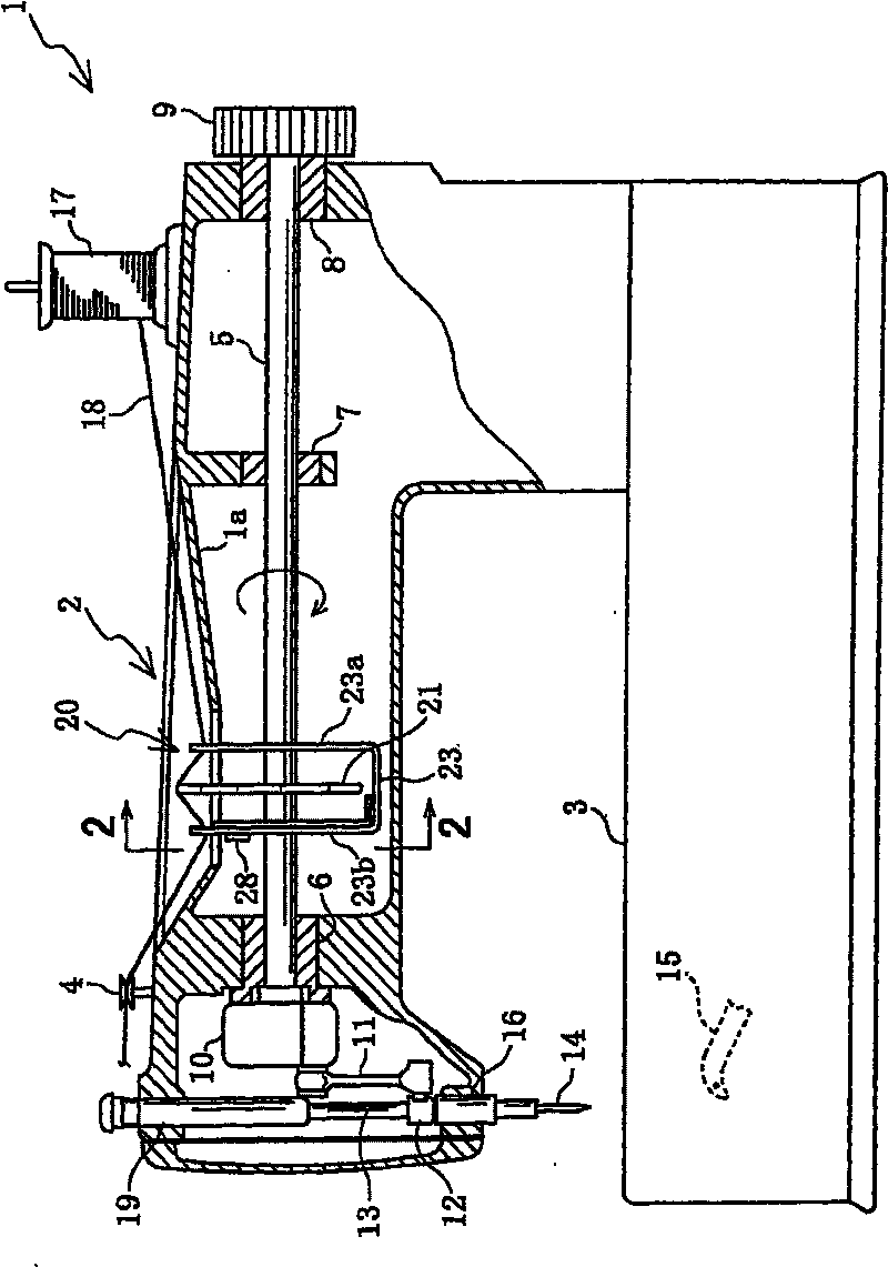
  • Thread ram means of sewing machine

Examples


Embodiment Construction

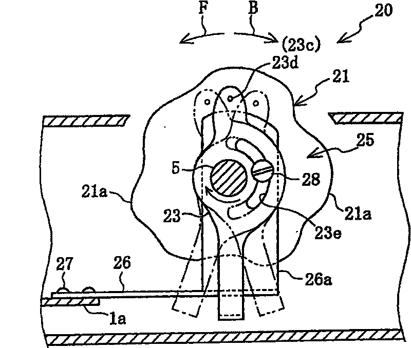
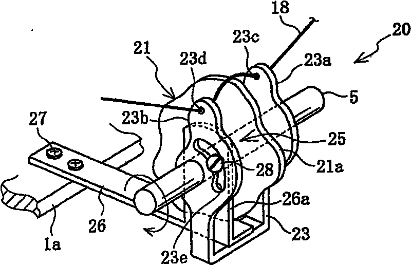
[0022] The thread take-up lever device of the sewing machine of this embodiment is provided with a concentric disc-type rotating thread take-up lever in the middle of the main shaft of the sewing machine provided on the arm of the double-chain stitch sewing machine with curved needles. The main shaft is equipped with guide plates of wire members on the left and right sides of the rotary thread take-up lever, and the wire members are rotatable centered on the main shaft of the sewing machine.

[0023] Refer below Figure 1 ~ Figure 5 The embodiment of the present invention is explained.

[0024] Such as figure 1 As shown, inside the arm 2 of the double chain stitch sewing machine 1, a sewing machine main shaft 5 (equivalent to a driving shaft integrally formed with the sewing machine main shaft 5) is arranged along its length direction (left and right direction), which is installed on the sewing mechanism frame 1a The upper bushings 6-8 are rotatably supported. A pulley 9 for manu...


PUM


Abstract

A thread take-up lever device of sewing machine is provided with a sewing machine main shaft arranged in the arm and a needle lever mechanism driven synchronize with the rotation of the sewing machinemain shaft. The device is characterized in that the device comprises a drive shaft which is integrated or separated with the sewing machine main shaft and can be driven rotatably synchronize with thesewing machine main shaft; a rotary thread take-up lever which is in round disc shape and has a thread take-up amount adjusting cam in outer circumferential part and is fixed not rotatable with the drive shaft; a thread guide member which is rotatably pivoted to the drive shaft and is formed with thread guide device which is used for guide needle thread supplied form a bobbin to engage the threadwith the thread take-up amount adjusting cam of the rotating thread take-up lever; and a phase adjusting mechanism circumferentially adjusting the phase of the thread guide device by turning the thread guide member around the drive shaft.

Description

Technical field [0001] The present invention relates to a thread take-up lever device for a sewing machine having a disc-shaped rotary thread take-up lever that is rotationally driven in synchronization with the main shaft of the sewing machine, and particularly relates to a structure capable of changing the phase of the thread take-up curve of the rotary thread take-up lever. Background technique [0002] In the past, sewing machines such as round head buttonhole sewing machines, double-chain stitch sewing machines, and decorative stitch sewing machines have curved needles. Generally speaking, these sewing machines are provided with a rotary thread take-up lever that rotates in conjunction with the main shaft of the sewing machine. A thread take-up amount adjusting cam is formed on the outer periphery of the rotary type thread take-up lever. With this thread take-up amount adjusting cam, the upper thread derived from the thread supply source can be drawn out or the looper threa...

Claims


Application Information

Patent Timeline
IPC IPC(8): D05B49/04D05B51/00D05B45/00D05B53/00
Inventor 西村和人铃木裕之野村悦造柴田到
Owner BROTHER KOGYO KK
Learn More