Turbine blade of turine and its puller

一种涡轮叶片、拔卸工具的技术,应用在叶片的支承元件、制造工具、金属加工等方向,能够解决加重、涡轮叶片损伤等问题,达到倾斜的危险减小、导入简化的效果

Inactive Publication Date: 2005-03-30
ANSALDO ENERGIA IP UK LTD
View PDF0 Cites 19 Cited by
  • Summary
  • Abstract
  • Description
  • Claims
  • Application Information

AI Technical Summary

Problems solved by technology

but this can cause damage to the turbine blades
In addition, when several turbine blades are hooked or coupled to each other by the outer shroud, the turbine blades must be removed from the anchoring slots almost simultaneously, thus exacerbating the aforementioned problems

Method used


Image

  • Turbine blade of turine and its puller
  • Turbine blade of turine and its puller
  • Turbine blade of turine and its puller

Examples


Embodiment Construction

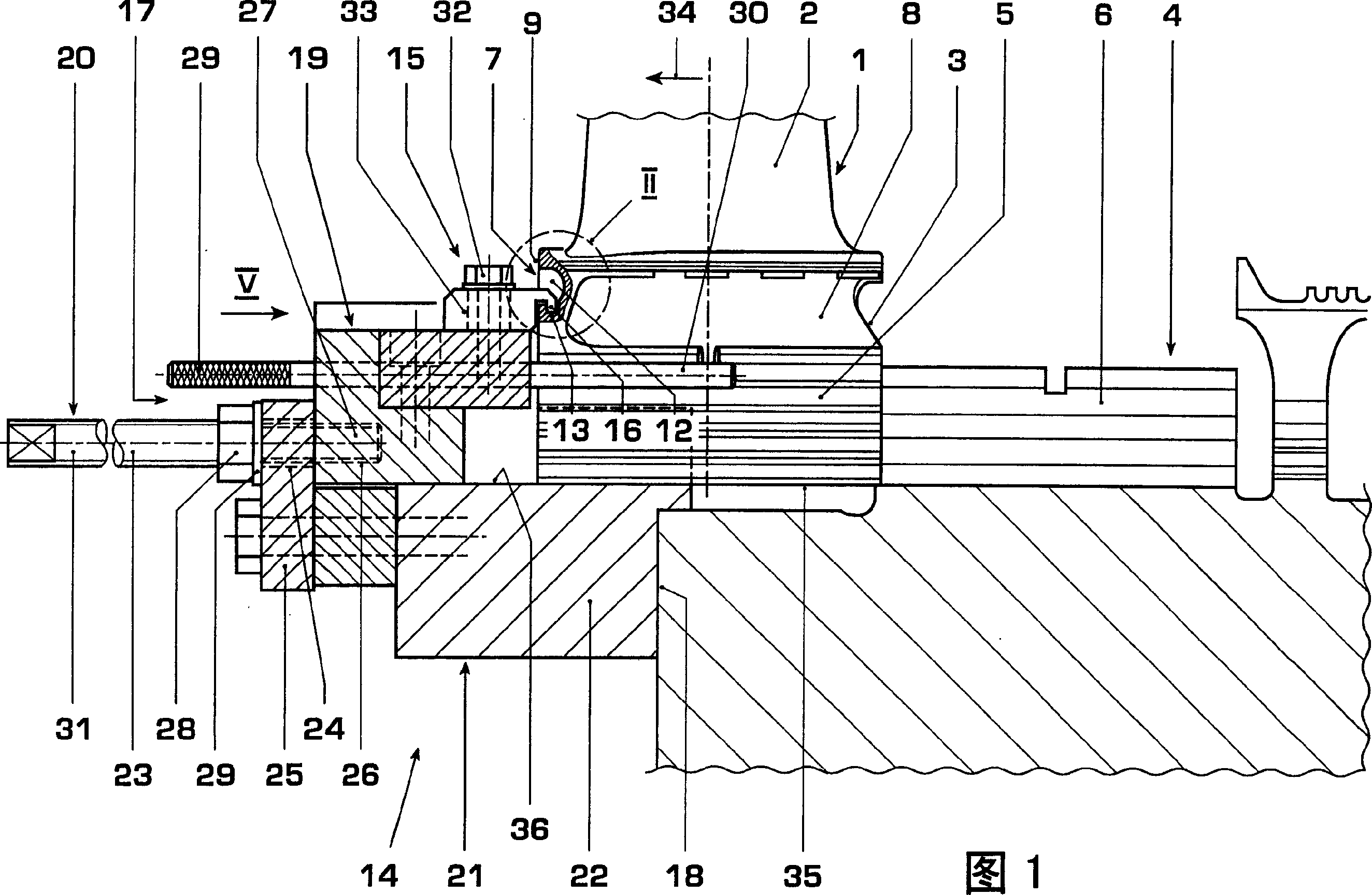
[0025] According to FIG. 1, the turbine blade 1 according to the invention has in the usual manner an aerodynamically shaped blade 2, which is used to guide the flow of air, and has a base 3, by which the turbine blade 1 can be fixed to a turbomachine, such as a gas turbine or a compressor. on rotor 4 of the machine. According to FIGS. 1 and 5 , on the base 3 on the side facing away from the blade 2 , for fastening purposes, an anchoring section 5 is formed, each having a Seed tooth portions, wherein these tooth portions converge in the direction of the axis of rotation of the rotor 4 . The profile of such a tooth portion may also be referred to as a "Christmas tree tooth".

[0026] According to FIG. 1 , the rotor 4 has, for each turbine blade 1 , an anchoring groove 6 extending axially, ie parallel to the axis of rotation of the rotor 4 , which is formed complementary to the anchoring section 5 of the turbine blade 1 . Correspondingly, the anchoring grooves 6 here also have...


PUM


Abstract

A turbine blade mounting with an improved pulling system for removing and fitting of the blade has the blade foot (3) sliding axially in a keyway (6) on the hub via a profiled grip (5) under the base. A puller (14) braced on the hub engages a lipped grip (7) on one side of the blade base to pull the blade along the keyway using a threaded drive. The blade is withdrawn without use of hammers and without damage to the interlocking grip and keyway. The lipped puller grip has a recess in the blade base fitted with lipped bottom edge formed by a rear groove.

Description

technical field [0001] The invention relates on the one hand to a turbine blade of a turbomachine and on the other hand to an extraction tool for removing such a turbine blade from a rotor of a turbomachine. Background technique [0002] Turbine blades usually have an aerodynamic blade and a base by which the turbine blade can be anchored in the rotor of the turbine. For this purpose, the base has, on its side facing away from the blade, an anchoring section which can be inserted axially into a complementary anchoring groove extending axially relative to the axis of rotation of the rotor. In this case, the shape of the anchoring section and the anchoring groove is matched to one another, so that a positive fit is formed between the anchoring section and the anchoring groove in the radial direction, by means of which the turbine blade is fixed or anchored radially. on the rotor. During operation of the rotor, especially in gas turbines, the turbine blades are subjected to h...

Claims


Application Information

Patent Timeline
Patent Type & Authority Applications(China)
IPC IPC(8): B25B27/02F01D5/00F01D5/30
CPCB23P6/002F01D5/005F01D25/285B25B27/023B23P19/025F05D2230/70F01D5/323F05B2230/70
Inventor 埃米尔·安纳爱德阿德·什劳茨基亚历山大·切卡诺夫雷米吉·查沃
Owner ANSALDO ENERGIA IP UK LTD
Why Eureka
Try Eureka