Device for fixing at least battery module at the bottom of a housing of a battery housing

A battery module and battery housing technology, applied in electric power devices, battery pack components, batteries, etc., can solve problems such as reducing rigidity, and achieve the effects of less deformation, less cost, and high aging resistance

Active Publication Date: 2019-03-12
VOLKSWAGEN AG
View PDF10 Cites 0 Cited by
  • Summary
  • Abstract
  • Description
  • Claims
  • Application Information

AI Technical Summary

Problems solved by technology

Another disadvantage is the relatively high number of screw connections known from the prior art, which is accompanied by a corresponding production cost of the battery
In addition, screw connections often pass through the module, which reduces its rigidity and makes it easier to deform

Method used


Image

  • Device for fixing at least battery module at the bottom of a housing of a battery housing
  • Device for fixing at least battery module at the bottom of a housing of a battery housing
  • Device for fixing at least battery module at the bottom of a housing of a battery housing

Examples


Embodiment Construction

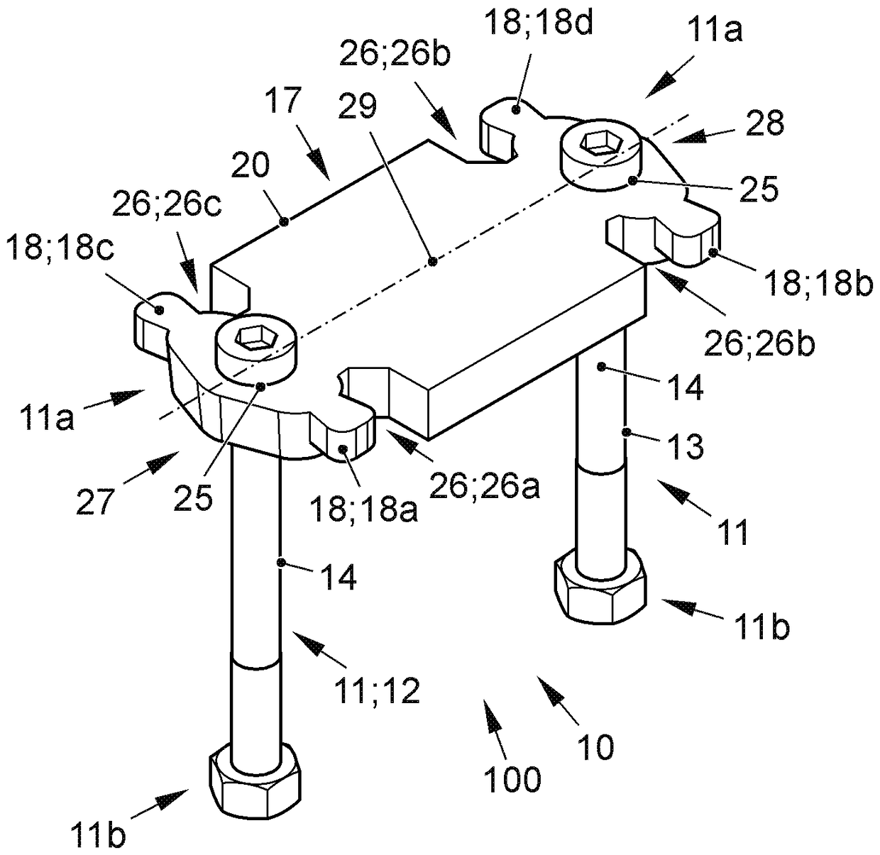
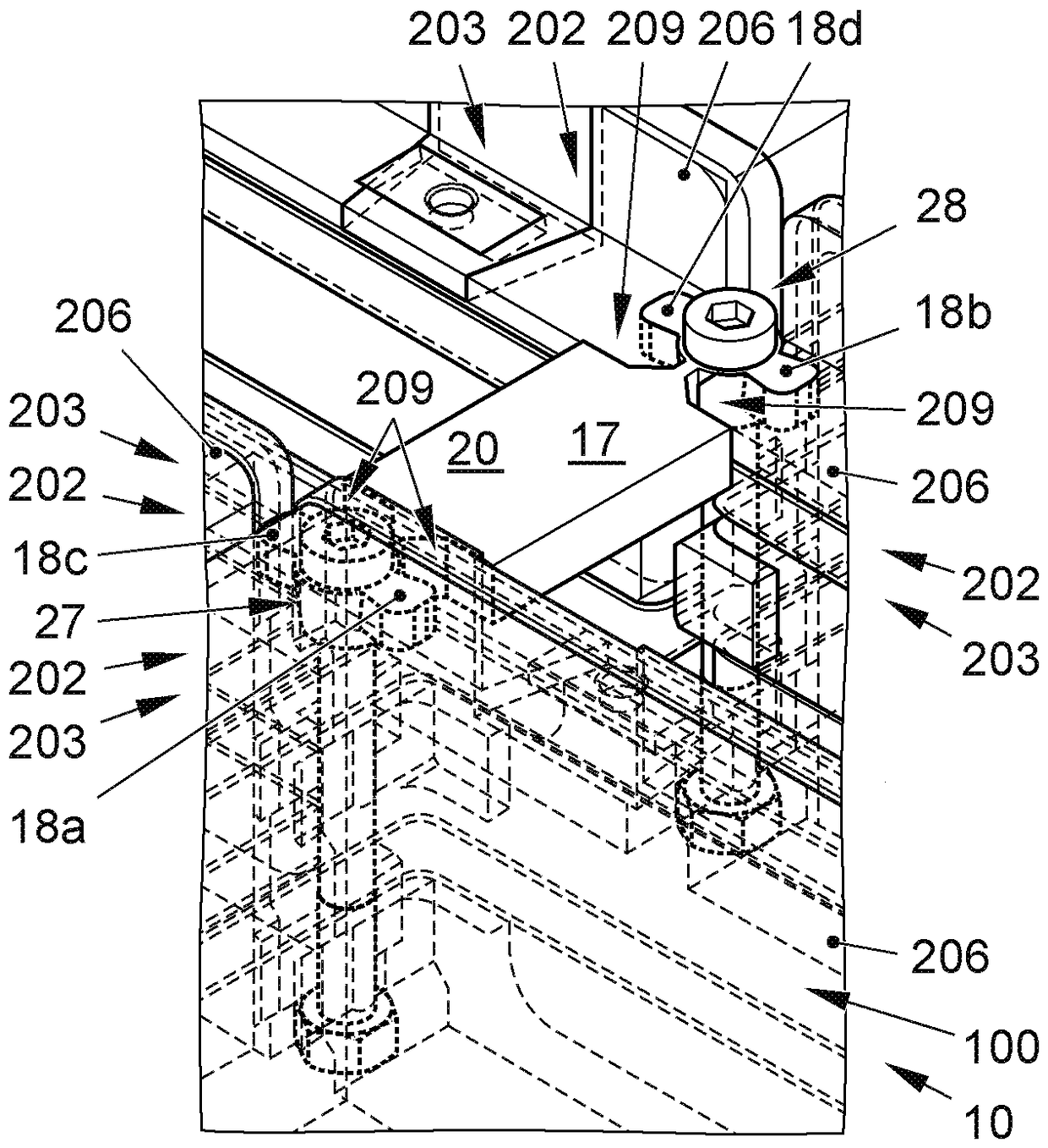
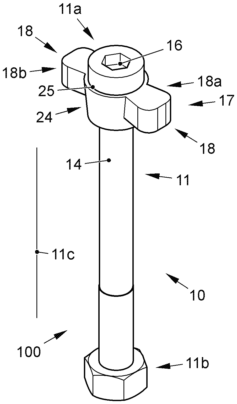
[0095] figure 1 A device (100) for fastening at least one battery module (202) on a housing bottom (201) of a battery housing (200) is shown. The fixing element (10) comprises a holding element (17) which has a bore (25). Furthermore, the fastening element (10) has a threaded fastener (11), which is guided through a bore (25) of the holding element (17). The holding element (17) has a projection (18) which extends in the lateral direction of the holding element (17) of the fixing element (10). The retaining element ( 17 ) extends eyelet-shaped or annular around the shank ( 14 ) of the threaded fastener ( 11 ), that is to say over the entire circumference. In other words, the retaining element (17) comprises a ring (24) from which the protrusion (18) protrudes.

[0096]The threaded fastener (11) has a first end region (11a) and a second end region (11b) and a longitudinal direction (11c). With regard to threaded fasteners, the protrusions extend into the radial direction. ...


PUM


Abstract

A device (100) for fixing at least one battery module (202) at the bottom (201) of a housing of a battery housing (200) is proposed, wherein the device (100) includes at least one fixing element (10)and wherein the fixing element (10) has a protrusion (18) for engaging into a recess (207) of the battery module housing (203) of the battery module (202).

Description

technical field [0001] The invention relates to a device according to claim 1 for fastening at least one battery module on a housing base of a battery housing and a battery housing according to claim 9 . Background technique [0002] In principle, it is known from the prior art that battery cells, for example lithium-ion cells (Lithium-Ionen-Zellen), must be protected against impacts. For this purpose, these lithium-ion cells must be combined in particular to form battery modules, which serve to fasten the individual cells and also (depending on the cell size) to reduce so-called swelling forces. The term "expansion" is to be understood in particular as the aging-induced expansion effect of individual cells. [0003] Furthermore, it is known to screw the battery module into the battery housing, but only acceleration forces are absorbed by known connection techniques. Additional forces acting on the modules in the event of a crash cannot be transmitted. If, in the event of...

Claims


Application Information

Patent Timeline
Patent Type & Authority Applications(China)
IPC IPC(8): H01M2/10B60K1/04H01M50/204H01M50/262H01M50/264
CPCB60K1/04H01M50/262H01M50/264F16B2/12H01M2220/20Y02E60/10
Inventor U.帕布斯特T.斯特赖恩K.博纳曼V.赫姆C.博克曼-古特分德H.赫特恩D.巴纳
Owner VOLKSWAGEN AG
Why Eureka
Try Eureka