Fan and blower unit having the fan

A fan and blade technology, applied in the field of blower units, can solve problems such as detailed location

Inactive Publication Date: 2005-04-06
DENSO CORP
View PDF1 Cites 7 Cited by
  • Summary
  • Abstract
  • Description
  • Claims
  • Application Information

AI Technical Summary

Problems solved by technology

However, the detailed position of the extension of

Method used


Image

  • Fan and blower unit having the fan
  • Fan and blower unit having the fan
  • Fan and blower unit having the fan

Examples


Embodiment Construction

[0019] Embodiments of the present invention will be described below with reference to the drawings.

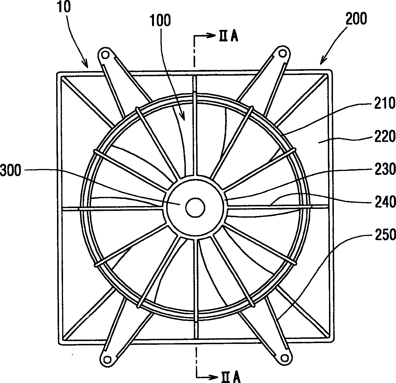
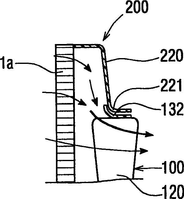
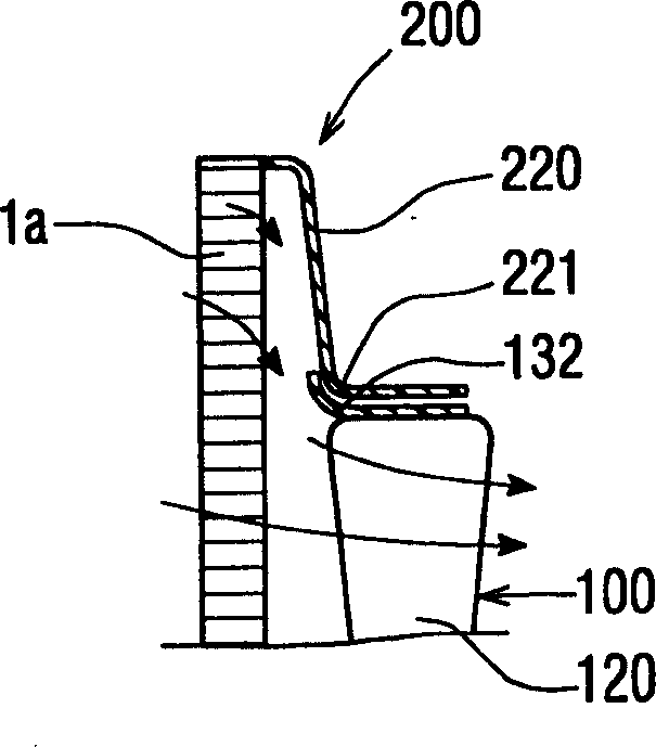
[0020] refer to figure 1 , the cooling fan 100 of the present invention is used in a blower unit (electric fan) 10 . The cooling fan 100 is accommodated in the cover 200 and driven by a motor 300 . The blower unit 10 is fixed to an engine side of a vehicle radiator (not shown) by four fixing portions 250 provided at corners of the cover 200 . Such as Figure 2A As shown in , the blower unit 10 generates a flow of cool air through the core 1a of the radiator. Here, the blower unit 10 is of suction type so that cooling air is drawn from the grill of the vehicle to the engine, ie, from the core 1 a of the radiator toward the cooling fan 100 .

[0021] The cooling fan 100 is an axial flow fan. The cooling fan 100 is manufactured from polypropylene which typically includes 20% glass fibers. Such as image 3 with 4 As shown in , the cooling fan 100 has a protruding portion 1...


PUM


Abstract

A cooling fan includes a cylindrical boss portion, a plurality of blades extending from the boss portion in a radial direction and a ring member integrated with radial outside edges of the blades. The ring member has an axial dimension smaller than an axial dimension of the blade at the radial outside edge, with respect to an axial direction of the boss portion. The ring member has an extending portion extending in a form of bell toward an upstream position of the blades with respect to an air flow. The extending portion is disposed such that a base point connecting to a body portion of the ring member is arranged in a range that begins at a point 25% and ends at a point 85% of a distance from an upstream end of the radial outside edge of the blade with respect to the axial dimension of the blade.

Description

technical field [0001] The invention relates to a fan having an annular part extending in the shape of a bell at the radially outer edge of the fan blades, and to a blower unit having such a fan. Background technique [0002] In the cooling fan of the blower unit, it is proposed to provide an annular member on the outer periphery of the fan blade, the annular member extending from the cylindrical protrusion portion in the radial direction. In the propeller fan disclosed in Japanese Utility Model Application Publication No. JP-U-62-152098, an annular portion as an air guide is integrally formed with a plurality of blades so that the annular portion extends linearly and is aligned with the radial direction of the blades. The outer edges touch. The fan does not form a gap between the ring portion and the radially outer edges of the blades, thereby reducing fan noise. In addition, the ring portion forms an extension in the form of a bell to improve air blowing efficiency and r...

Claims


Application Information

Patent Timeline
IPC IPC(8): F04D29/38F04D29/32F04D29/54
CPCF04D29/326F04D25/08F04D29/545F04D29/38F04D29/541F04D29/002F04D29/403F05D2210/12Y10S415/00Y10S417/00
Inventor 岩崎卓洋宇佐见卓也
Owner DENSO CORP
Why Eureka
Try Eureka