Blower apparatus

a blower and air technology, applied in the field of blower apparatus, can solve the problems of reducing the air blowing efficiency of the blower apparatus, reducing the width of a space, and reducing the air blowing efficiency, so as to reduce noise and improve air blowing efficiency

Inactive Publication Date: 2018-08-23
NIPPON DENSAN CORP
View PDF5 Cites 7 Cited by
  • Summary
  • Abstract
  • Description
  • Claims
  • Application Information

AI Technical Summary

Benefits of technology

[0006]The blower apparatus according to the above preferred embodiment of the present invention is able to achieve reduced noise and improved air blowing efficiency.

Problems solved by technology

A reduction in the thickness of a blower apparatus leads to a reduction in the axial dimension of blade portions and a reduction in an area of each blade portion which is involved in driving away air, resulting in reduced air blowing efficiency of the blower apparatus.
However, this will result in a reduced width of a space between radially inner end portions of circumferentially adjacent ones of the blade portions.
This will make it difficult for air sucked into the blower apparatus to flow into the aforementioned space, resulting in reduced air blowing efficiency.
In addition, when an impeller is rotating, the sucked air may separate from a surface of each blade portion to flow between adjacent ones of the blade portions and a housing or turn into an eddy, resulting in increased noise.

Method used


Image

  • Blower apparatus
  • Blower apparatus
  • Blower apparatus

Examples


Embodiment Construction

[0024]Hereinafter, preferred embodiments of the present invention will be described with reference to the accompanying drawings.

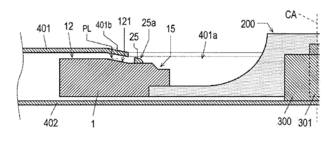
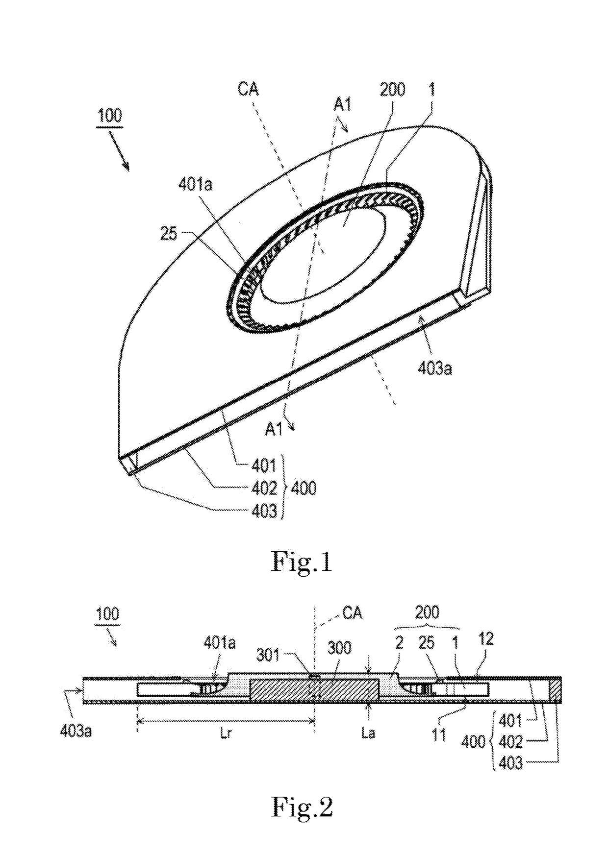
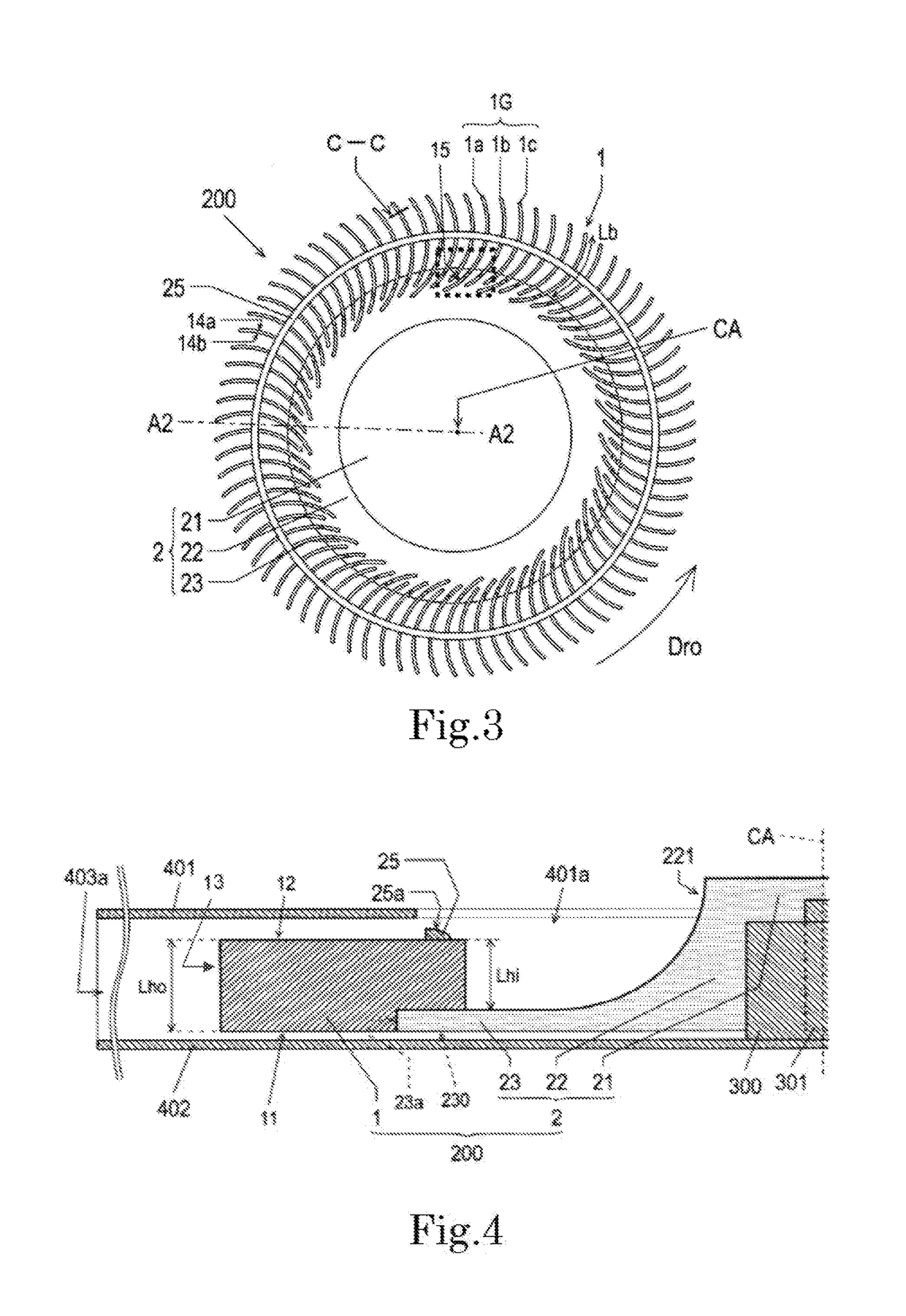
[0025]It is assumed herein that a direction parallel to a central axis CA of a blower apparatus 100 is referred to by the term “axial direction”, “axial”, or “axially”. It is also assumed herein that a direction leading from a support plate portion 402, which will be described below, to an intake plate portion 401, which will be described below, in an axial direction is referred to as an upward direction. It is also assumed herein that a direction leading from the intake plate portion 401 to the support plate portion 402 in the axial direction is referred to as a downward direction. It is also assumed herein that an end portion of any structural element on an axially upper side is referred to as an “upper end portion”, while an end portion of any structural element on an axially lower side is referred to as a “lower end portion”. It is also assumed herein t...


PUM


Abstract

A blower apparatus includes an impeller arranged to be capable of rotating about a central axis extending in a vertical direction, and a motor arranged to drive the impeller. The impeller includes a plurality of blade portions arranged in a circumferential direction, and a flange portion arranged to have the blade portions arranged on an outer peripheral portion thereof on a radially outer side. At least one of the blade portions includes a shoulder portion at an end portion thereof on a radially inner side and on one axial side. The shoulder portion includes a first end surface arranged to face to the one axial side, a second end surface arranged to face to the one axial side and arranged on another axial side of the first end surface, and a third end surface arranged to join an inner end portion of the first end surface on the radially inner side and an outer end portion of the second end surface on the radially outer side to each other.

Description

BACKGROUND OF THE INVENTION1. Field of the Invention[0001]The present invention relates to a blower apparatus.2. Description of the Related Art[0002]A blower apparatus is known which is arranged to send air radially outward by using a motor to rotate a plurality of blade portions about an axis. Such a blower apparatus is arranged to send air which flows from, for example, an air inlet arranged on an axially upper side into a space between circumferentially adjacent ones of the blade portions radially outward through rotation of the blade portions to send the air to a space outside of the blower apparatus. Such a blower apparatus is used as, for example, a cooling fan in an electronic device which is required to have a reduced thickness.[0003]Japanese Patent No. 5012096 teaches an electric blower including an impeller including a plurality of blades, which is a related-art blower related to the present invention. In this electric blower, a radially outermost end portion of each blade...

Claims


Application Information

Patent Timeline
Patent Type & Authority Applications(United States)
IPC IPC(8): F04D29/28F04D25/06F04D29/30F04D29/42F04D29/66
CPCF04D29/283F04D25/06F04D29/30F04D29/4226F04D29/666G06F1/203H05K7/20136F04D25/0606F04D29/162F04D29/282
Inventor TAMAOKA, TAKEHITOHIRAYAMA, MASASHIHORAITANI, NARUYUKIHIRANO, SHUNITO, TAKAYUKI
Owner NIPPON DENSAN CORP
Why Eureka
Try Eureka