Blower apparatus

a technology of blower and air filter, which is applied in the direction of positive displacement liquid engine, piston pump, liquid fuel engine, etc., can solve the problem of insufficient air blowing efficiency and achieve the effect of convenient fixing

Inactive Publication Date: 2017-12-14
NIPPON DENSAN CORP
View PDF5 Cites 6 Cited by
  • Summary
  • Abstract
  • Description
  • Claims
  • Application Information

AI Technical Summary

Benefits of technology

[0010]According to the above preferred embodiment of the present invention, relative circumferential positions of the flat plates can be easily fixed ...

Problems solved by technology

Accordingly, a reduction in the thickness of the blower apparatus, which involves a reduction in t...

Method used


Image

  • Blower apparatus
  • Blower apparatus
  • Blower apparatus

Examples


Embodiment Construction

[0025]Hereinafter, blower apparatuses according to preferred embodiments of the present, invention will be described. It is assumed herein that a side on which an upper plate portion is arranged with respect to a lower plate portion is an upper side, and the shape of each member or portion and relative positions of different members or portions will be described based on the above assumption. It should be noted, however, that the above definition of the upper and lower sides is not meant to restrict in any way the orientation of a blower apparatus according to any preferred embodiment of the present invention at the time of manufacture or when in use.

1. FIRST PREFERRED EMBODIMENT

[0026]1-1. Structure of Blower Apparatus

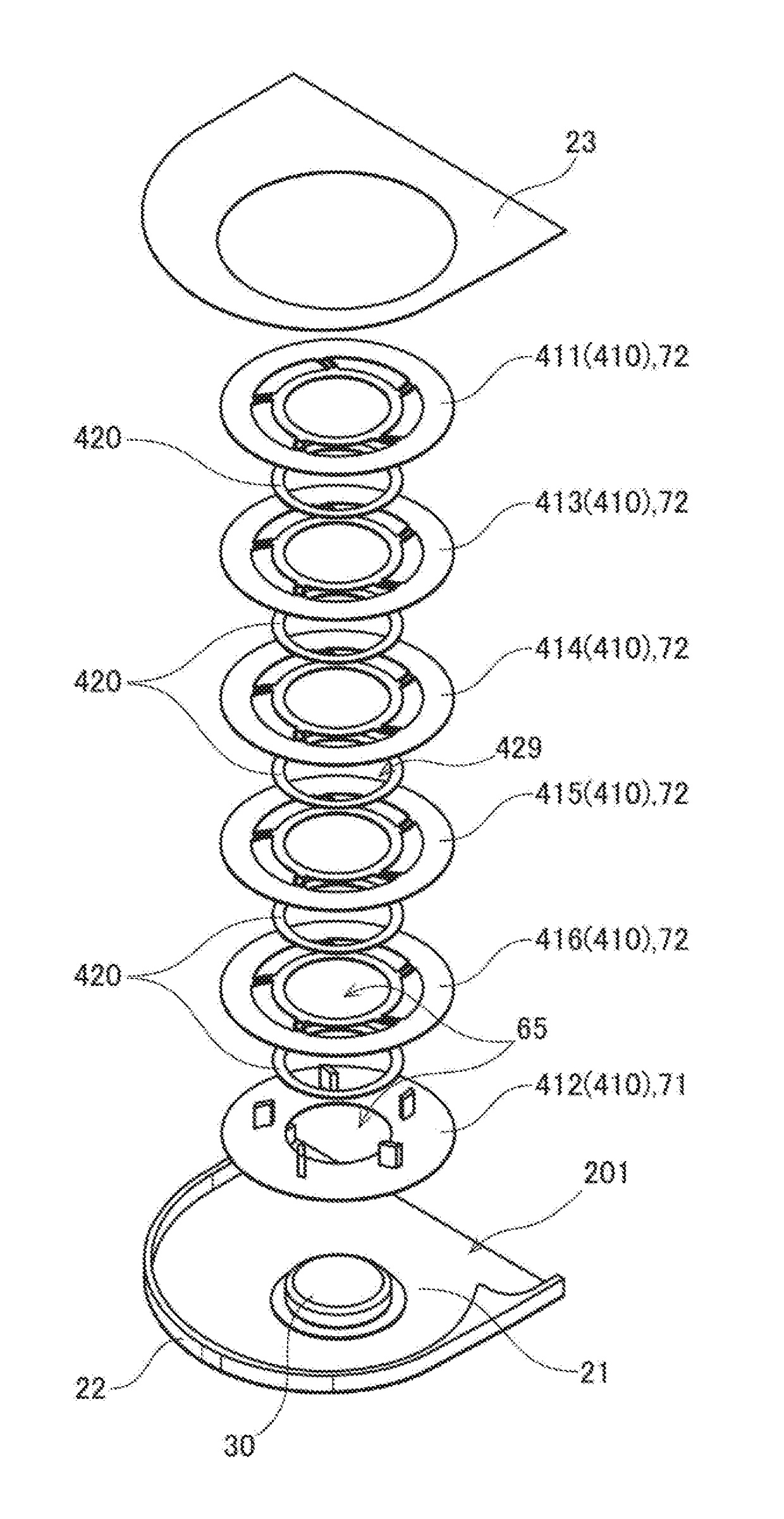
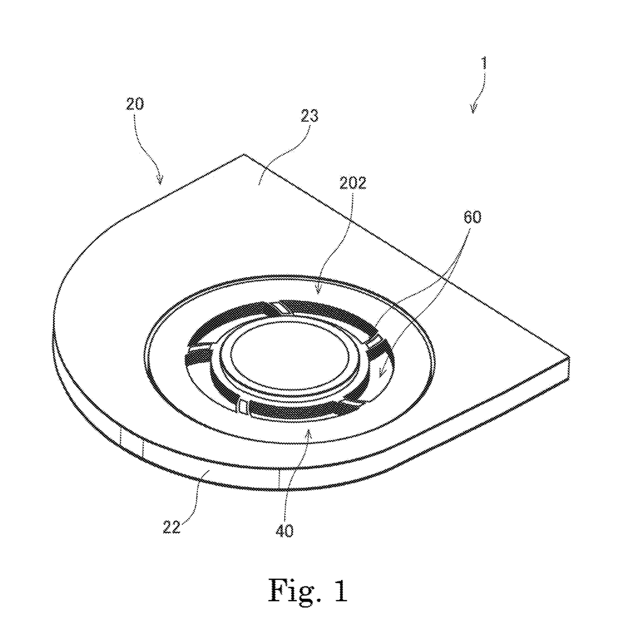
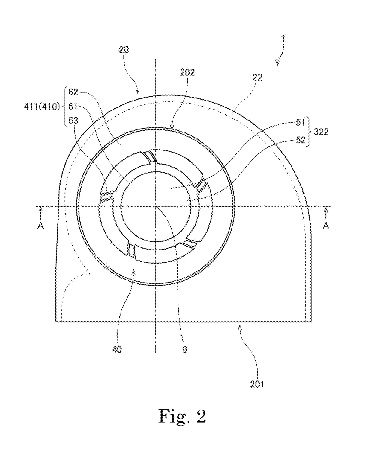
[0027]FIG. 1 is a perspective view of a blower apparatus 1 according to a first preferred embodiment of the present invention. FIG. 2 is a top view of the blower apparatus 1. FIG. 3 is a sectional view of the blower apparatus 1 taken along line A-A in FIG. 2. FIG. 4 is...


PUM


Abstract

This blower apparatus includes an air blowing portion including a plurality of flat plates arranged with an axial gap defined between adjacent ones of the flat plates; a motor portion arranged to rotate the air blowing portion; and a housing arranged to house the air blowing portion and the motor portion. The housing includes an air inlet arranged to pass through a portion of the housing in an axial direction above the air blowing portion, and an air outlet arranged to face in a radial direction radially outside of the air blowing portion. One of the flat plates includes a projecting portion arranged to project upward and/or downward, and another one of the flat plates includes an opposing portion arranged to be circumferentially opposed to the projecting portion. Relative circumferential positions of the flat plates can be easily fixed by the opposing portion.

Description

BACKGROUND OF THE INVENTION1. Field of the Invention[0001]The present invention relates to a blower apparatus.2. Description of the Related Art[0002]A centrifugal blower apparatus which generates an air flow traveling radially outward by rotating an impeller including a plurality of blades is known. A known blower apparatus including an impeller is described in, for example, JP-A 2008-88985.[0003]In the blower apparatus described in JP-A 2008-88985, a plurality of blades referred to as fan blades push surrounding gas to generate air flows traveling radially outward.SUMMARY OF THE INVENTION[0004]In recent years, there has still been a demand for reductions in the size and thickness of electronic devices. Accordingly, there has also been a demand for a reduction in the thickness of blower apparatuses used to cool the interiors of the electronic devices.[0005]Here, in the case where an impeller is used to generate air flows, as in the blower apparatus described in JP-A 2008-88985, air ...

Claims


Application Information

Patent Timeline
IPC IPC(8): F04D29/62F04D29/08F04D25/06F04B35/04F04B17/00
CPCF04D29/626F04B35/04F04B17/00F04D29/083F04D25/06F04D17/08F04D29/056F04D29/063F04D29/4206F04D17/161F04D25/0613
Inventor HINO, YUKOYOO, SEUNG-SINTSUKAMOTO, TOMOYUKIMAKITA, AKIHIKO
Owner NIPPON DENSAN CORP
Why Eureka
Try Eureka