Chemical liquid supplying device and method for venting air

一种化学液体、设备的技术,应用在化学液体供应设备领域,能够解决化学液体分配量不稳定、分配精度下降等问题

Inactive Publication Date: 2005-04-20
KOGANEI
View PDF2 Cites 13 Cited by
  • Summary
  • Abstract
  • Description
  • Claims
  • Application Information

AI Technical Summary

Problems solved by technology

[0004] If air bubbles are mixed in the equipment during the dispensing of chemical liquids such as photoresist liquids, the air bubbles absorb the pressure of extruding the chemical liquid, making the dispensed amount of the chemical liquid unstable, thereby reducing its dispensing accuracy

Method used


Image

  • Chemical liquid supplying device and method for venting air
  • Chemical liquid supplying device and method for venting air
  • Chemical liquid supplying device and method for venting air

Examples


Embodiment Construction

[0026] Hereinafter, embodiments of the present invention will be described in detail based on the accompanying drawings.

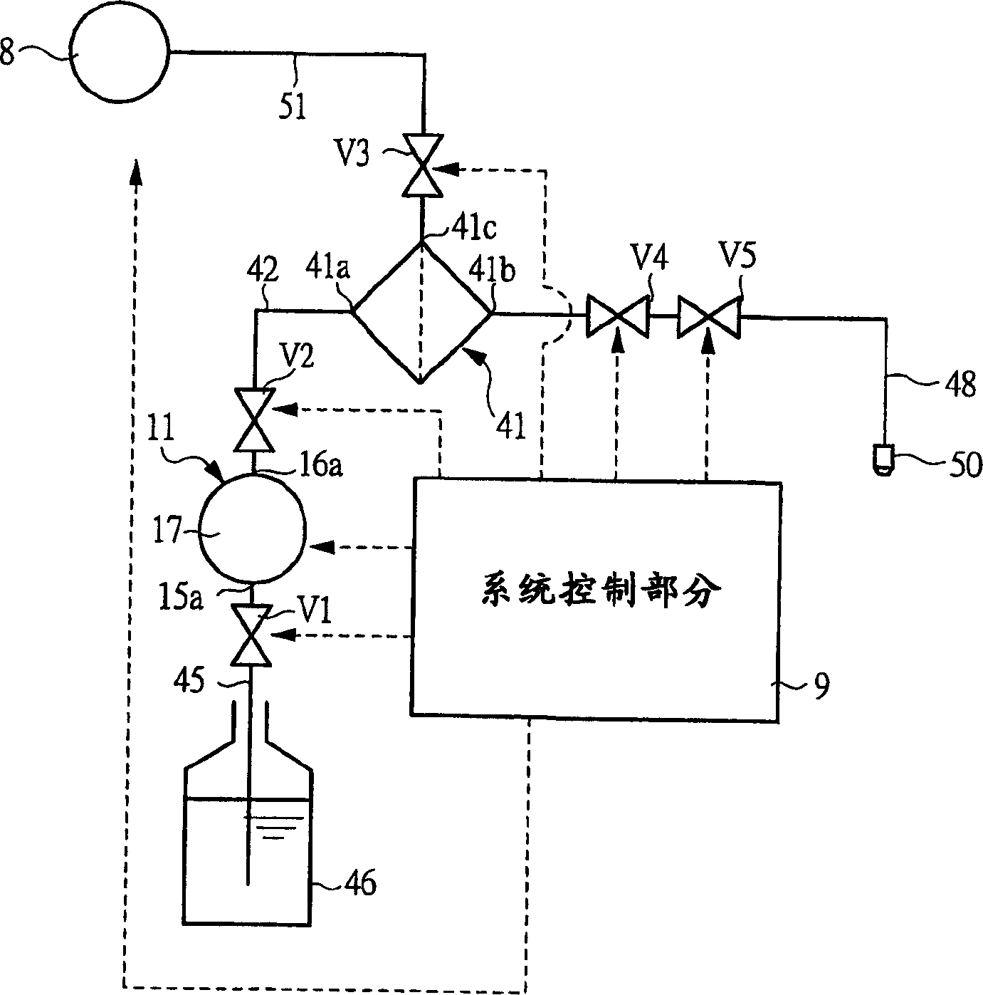
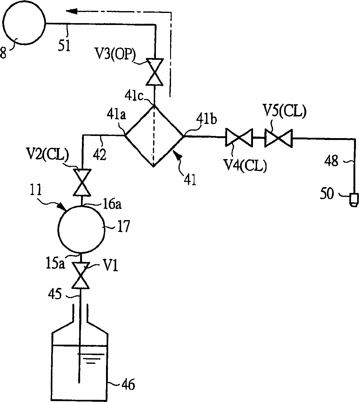
[0027] figure 1 is a liquid circuit diagram schematically showing a chemical liquid supply device according to an embodiment of the present invention. Such as figure 1 As shown, the chemical liquid supply equipment includes: a pump 11 for discharging liquid contained in a liquid tank 46; a filter 41 connected to the pump 11 through a pump outlet flow path 42, wherein the pump outlet flow path is set There is a pump discharge side valve V2 for opening / closing the flow path; a dispensing nozzle (liquid discharge portion) 50 connected to the filter 41 through a liquid discharge flow path 48 provided for opening / closing The discharge valve V4 of the flow path; the vacuum source 8 communicated with the filter 41 through the exhaust flow path 51, wherein the exhaust flow path is provided with a degassing valve V3 for opening / closing the flow path. The structu...


PUM


Abstract

The present invention relates to a chemical liquid supply device and a degassing method. The pump (11) discharges the liquid contained in the liquid tank (46). The filter (41) is connected to the pump (11) through a pump outlet flow path (42) provided with a pump discharge side valve (V2) for opening and closing the flow path. The dispensing nozzle (liquid discharge part) (50) is connected to the filter (41) through a liquid discharge flow path (48) provided with a discharge valve (V4 ). A vacuum source (8) communicates with the filter (41) through an exhaust flow path (51) provided with a degassing valve (V3) for opening and closing the flow path.

Description

technical field [0001] The present invention relates to a chemical liquid supply device for discharging a predetermined amount of liquid such as a chemical liquid, for example a chemical liquid supply device and a degassing method thereof, which are suitable for coating a photoresist liquid on the surface of a semiconductor wafer ( photoresist liquid). Background technique [0002] In each manufacturing process in various technical fields, such as semiconductor wafer manufacturing technology, liquid crystal display manufacturing technology, magnetic disk manufacturing technology, and multilayer printed circuit board manufacturing technology, chemical liquids such as photoresist liquid, spinning (spin-on) glass liquid, polyimide resin liquid, pure water, developer, etchant, cleaning liquid or organic solvent, and use chemical liquid supply equipment to apply these chemical liquids. For example, a chemical liquid supply apparatus disclosed in US Pat. No. 5,061,156 has been de...

Claims


Application Information

Patent Timeline
Patent Type & Authority Applications(China)
IPC IPC(8): B01D19/00B01J4/00B05C11/10F04B53/06G03F7/16G03F7/30G03F7/40G03F7/42H01L21/027
CPCB01D19/0031B01D19/0068G03F7/16G03F7/162G03F7/3021G03F7/40G03F7/422
Inventor 宇田川诚一郎
Owner KOGANEI
Why Eureka
Try Eureka