
Under-counter water cooler appliance

a water cooler and under-counter technology, applied in the direction of liquid dispensing, liquid transferring device, packaging, etc., can solve the problems of large space occupation of the dispensing system, unsuitable use in the household kitchen, and the inability to use the dispensing system

Inactive Publication Date: 2010-05-13
DESIGN BY PARI
View PDF28 Cites 36 Cited by
  • Summary
  • Abstract
  • Description
  • Claims
  • Application Information

AI Technical Summary

Benefits of technology

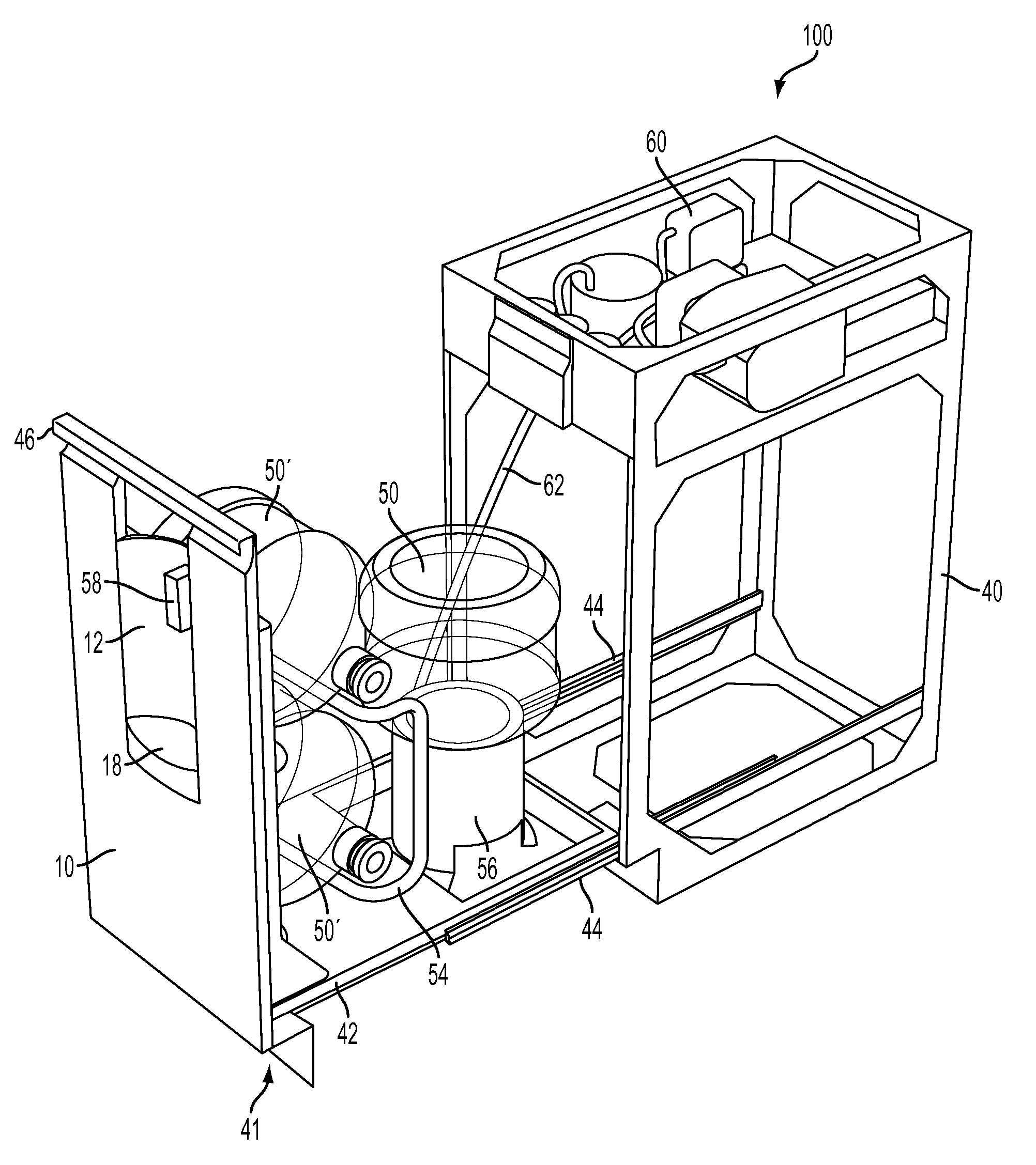
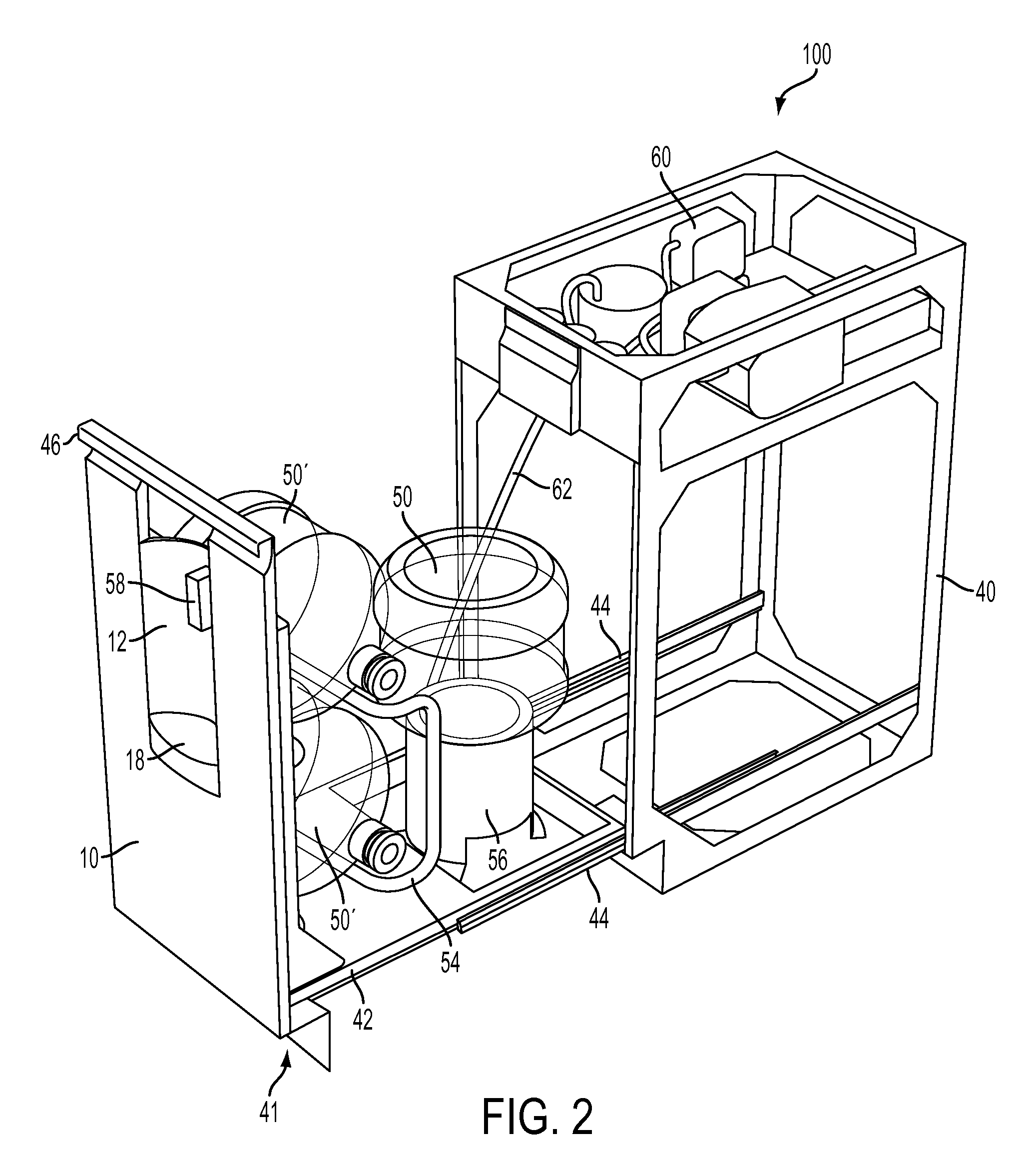
"The present invention is an appliance for dispensing liquid to a user. The appliance includes a base cabinet with an enclosure positioned under a counter. A dispenser spigot is coupled to the base cabinet at a suitable distance below the counter. A liquid storage tank is supported by the support member of the appliance base cabinet and has an opening for out-flow of the liquid. An intermediate reservoir is positioned between the liquid storage tank and the dispenser spigot to channel the liquid from the tank to the spigot. The liquid storage tank may be oriented in an inverted position, upright position, or slanted position relative to ground. The appliance may also include a pump to pump the liquid from the tank, an intermediate reservoir, a piercing device to enable the flow of liquid from the tank, a chilling device to cool the liquid, a heating device to heat the liquid, and valves to deliver different temperatures of liquid to the spigot. The appliance may also have an indicator device to indicate the dispensing of the liquid and an activator device to allow the user to activate the dispensing. The appliance base cabinet may also include a child lock-out device."

Problems solved by technology

These known fluid dispensing systems suffer from a number of drawbacks which makes them unsuitable for use in a household kitchen.
For example, these fluid dispensing systems usually occupy a large amount of space, are unsightly, and detract from the stylistic design of a kitchen.
Further, it is often difficult to remove and replace one or more empty water bottles from the fluid dispensing systems without heavy and strenuous lifting by the user.

Method used


Image

  • Under-counter water cooler appliance
  • Under-counter water cooler appliance
  • Under-counter water cooler appliance

Examples


Embodiment Construction

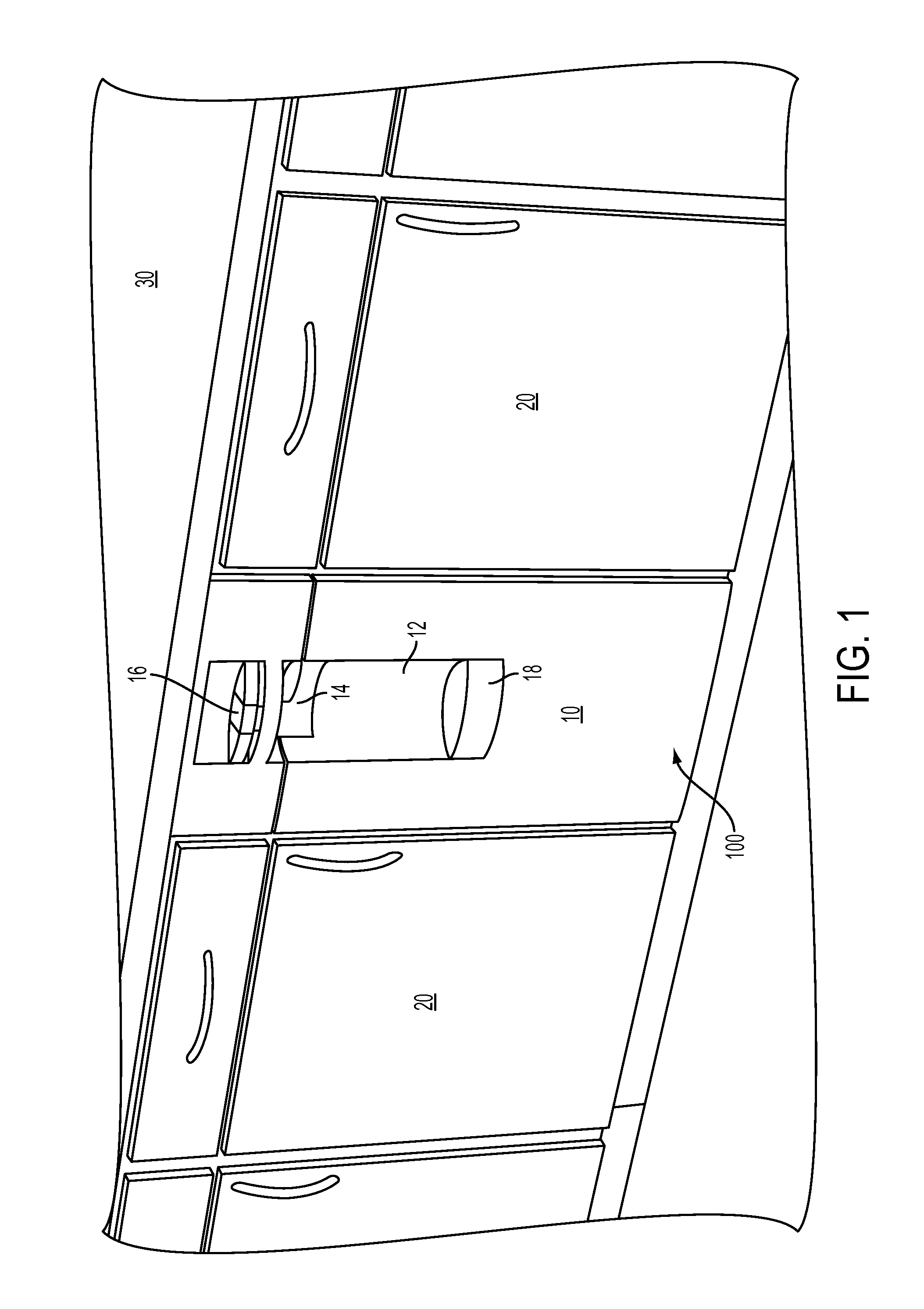
[0029]Referring to FIG. 1, the present invention relates generally to a liquid dispensing appliance 100 that fits under a kitchen counter 30 within a suitably sized cabinet opening (for example, a standard base cabinet opening). The counter 30 may be a kitchen counter and / or a bar counter and may further be fixed to a wall 32, as shown in FIG. 6. In this way, the present invention allows for integration of the liquid dispensing appliance 100, i.e. a liquid dispensing appliance base cabinet, with other kitchen appliances, thereby providing a uniform and aesthetic appearance to the kitchen, as well as convenience for dispensing a liquid, for example water, in such kitchen.

[0030]The size of the liquid dispensing appliance 100 can be specified according to United States or international standards that govern household appliances, for example standards specified by American National Standards Institute (ANSI) or the Association of Home Appliance Manufacturers (AHAM), which represents the...


PUM


Abstract

An appliance for dispensing a liquid to a user, including an appliance base cabinet comprising an enclosure positioned under a counter that is fixed to a wall. The appliance base cabinet having a support member that is moveable relative to the counter. At least one dispenser spigot is coupled to the appliance base cabinet at a suitable distance below the counter to allow a user dispense water via the at least one dispenser spigot. At least one liquid storage tank is supported by the support member having an opening for out-flow of the liquid. The at least one liquid storage tank is accessible for removal or installation when the support member is moved away from the kitchen counter. The appliance further includes an intermediate reservoir within the appliance base cabinet under the kitchen counter coupled to the opening of the at least one liquid storage tank through which the liquid out of the at least one liquid storage tank is channeled to the at least one dispenser spigot.

Description

CROSS-REFERENCE TO RELATED APPLICATION[0001]This application claims the priority of Provisional Application No. 61 / 112,299, filed on Nov. 7, 2008, the subject matter of which is incorporated herein by reference.FIELD OF THE INVENTION[0002]This invention relates generally to liquid dispensers, and in particular, to drinking liquid dispensers for bottled liquids in which the bottle is housed in a modular appliance base cabinet located beneath a kitchen counter.BACKGROUND OF THE INVENTION[0003]The distribution of bottled liquids is widely used in offices and homes throughout the world. For example, U.S. Pat. No. 2,744,660 to Jacobs discloses an apparatus for displaying and dispensing fruit juices, milk, and similar beverages in a tank preferably made of glass or other transparent material, mounted on a cabinet. A dispensing valve controlled by a handle, is mounted on the side of the cabinet and connected by piping to the tank.[0004]U.S. Pat. No. 3,269,143 to Gasparovich discloses a liq...

Claims


Application Information

Patent Timeline
Patent Type & Authority Applications(United States)
IPC IPC(8): B67D7/84
CPCB67D1/0004B67D1/06B67D1/0869B67D1/0891B67D2210/00031B67D2210/00097B67D2210/00118
Inventor FOROUGHI, PARVANEH MOVAHEDFOROUGHI, KHOSROWBYAR, PETERCOLEMAN, JOHNWEIMAN, ANDREW
Owner DESIGN BY PARI
Learn More