
Liquid-drop discharge device

Inactive Publication Date: 2002-09-03
NGK INSULATORS LTD
View PDF9 Cites 37 Cited by
  • Summary
  • Abstract
  • Description
  • Claims
  • Application Information

AI Technical Summary

Benefits of technology

With this arrangement, liquid may be discharged in a steady and well-controlled manner despite the presence of air bubbles in liquid within the flow path, wherein the flow of liquid applied with minute oscillation by the oscillating means is atomized, and atomization caused through suction of the air-contacting surface of the discharge outlet by the internal pressure of the reaction cell may be continued while maintaining a minute spraying condition. When the internal pressure of the liquid storage tank and the internal pressure of the reaction cell are identical, spraying of a small amount may be performed even through fibrillation of the oscillating means, so that it is possible to cope with various amounts of spraying of a wide range from a large capacity to a small amount.
It should be noted that as an exemplary means for setting the internal pressure P3 of the reaction cell to be not more than the internal pressure P1 of the liquid storage tank, air is supplied to the reaction cell, and if necessary, a negative pressure may be effectively achieved by narrowing a sectional surface area of a portion of the reaction cell that is open to the discharge outlet in contrast to other portions.
The present invention further relates to a liquid-drop discharge device wherein the liquid discharge means comprises a discharge outlet provided at an end of a flow path opening to the reaction cell, and an oscillating means concurrently provided with a function of adjusting an opening degree of the discharge outlet and of applying fibrillation to liquid introduced into the flow path through the discharge outlet. With this arrangement, it is possible to simplify arrangements of driving portions and to decrease manufacturing costs for performing atomization in an effective manner.
With this arrangement, it is possible to perform discharge at low electric consumption and in a well-controlled manner, and to further decrease manufacturing costs. When the opening degree means is concurrently provided as the oscillating means, it is favorably possible to perform high-frequency oscillation and to perform rapid adjustment of the opening degree. In order to enable large displacements of the thin film portion of the wall portion of the flow path for adjusting the opening degree, it is possible to form the end portion of the flow path to be wide in a direction orthogonal to a direction of displacement and to provide the discharge outlet in a center thereof as the end portion of the flow path.
The oscillating means may be comprised of a laminated actuator or a thin film actuator, which is arranged to pinch piezoelectric bodies between cathodes and anodes, outside of the thin film portion of the wall portion of the flow path. It is particularly preferable that the liquid discharge means be comprised of a flow path having a wall surface with at least one surface thereof being arranged to be thinner than remaining surfaces, and that the oscillating means be arranged to apply minute oscillation to liquid by utilizing distortion of a piezoelectric / electrostrictive element provided at least at one portion of the thin wall portion of the flow path. With this arrangement, it is not only possible to provide an oscillating means of large amplitude at low costs, but also to perform high-frequency driving at low voltage.
It is preferable that the discharge outlet be arranged in that its portion opening to the reaction cell is formed to assume a shape of an elongated hole for increasing a surface area of discharge and an amount of spraying. It is also preferable to dispose a float cell that is connected to between the liquid storage tank and the liquid discharge means with a check valve being formed at the liquid storage tank for functioning to maintain a constant liquid surface with a constant capacity. The back pressure of the liquid from the liquid storage tank may thus be made constant and leakage of liquid from the discharge outlet upon being pressurized may be prevented.

Problems solved by technology

However, such discharge devices are used in offices or schools under relatively stationary conditions with little fluctuations in temperature or pressure of peripheral environments when being used, and are not exposed to significant fluctuations in operating environments.
While remarkable fluctuations in environments of discharge spaces are likely to occur at the time of operating such devices, due to fluctuations in operating conditions or the like, it is presently the case that no device has yet been proposed with which liquid can be supplied as minute particles in a desirable manner even though in the presence of fluctuations in discharge spaces.

Method used


Image

  • Liquid-drop discharge device
  • Liquid-drop discharge device
  • Liquid-drop discharge device

Examples


Embodiment Construction

Forms for embodying the liquid-drop discharge device according to the present invention will now be explained in detail.

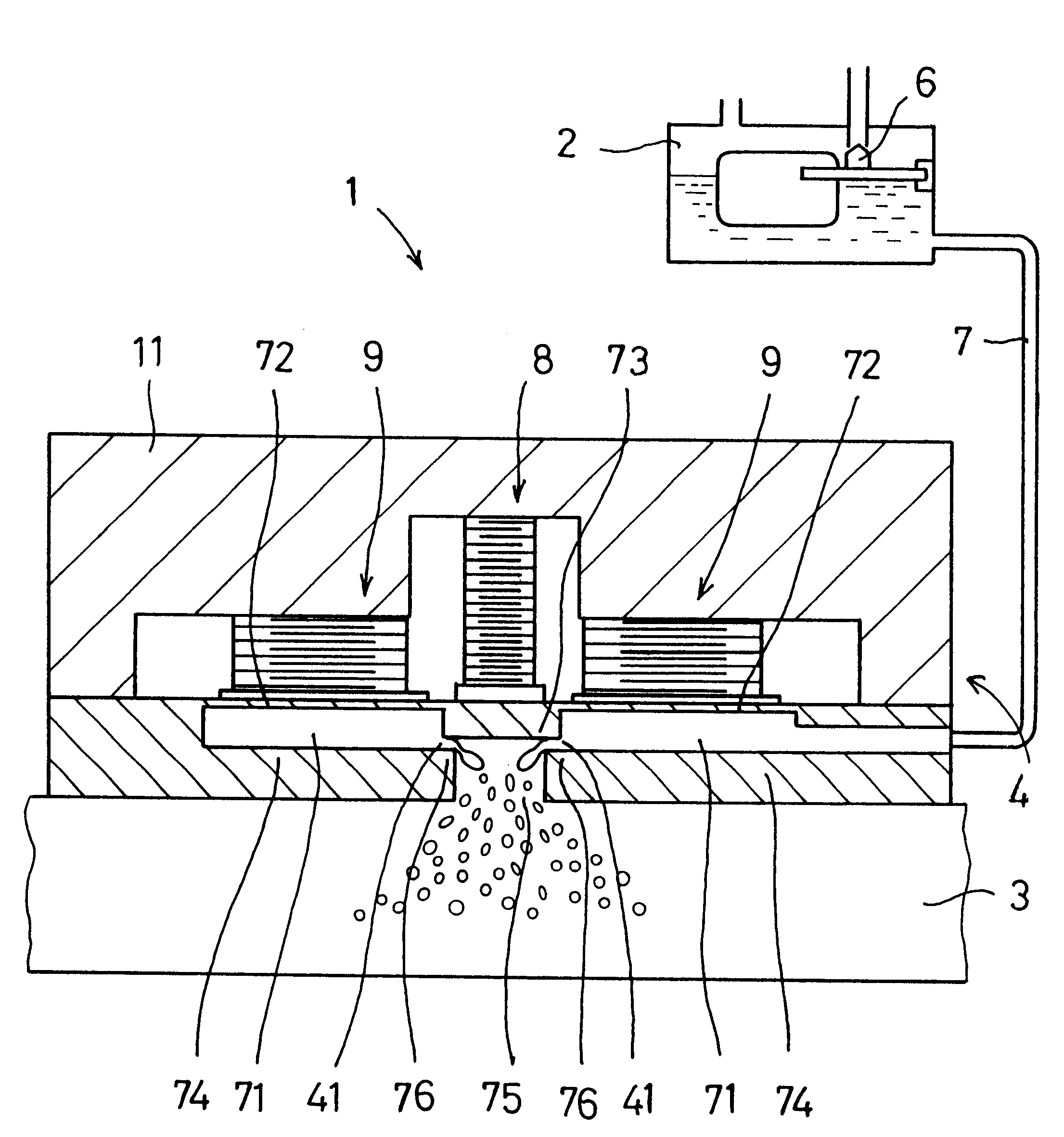
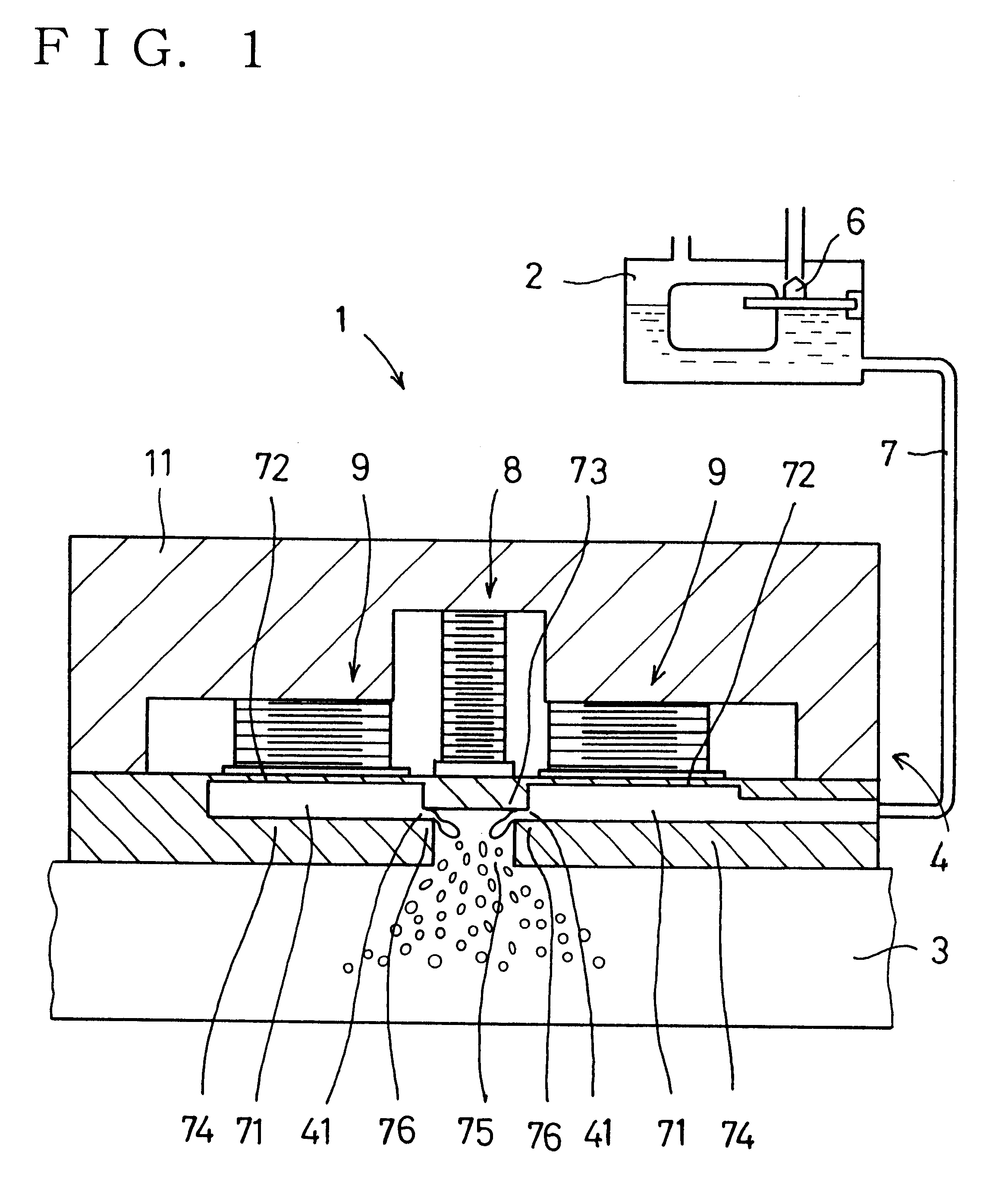
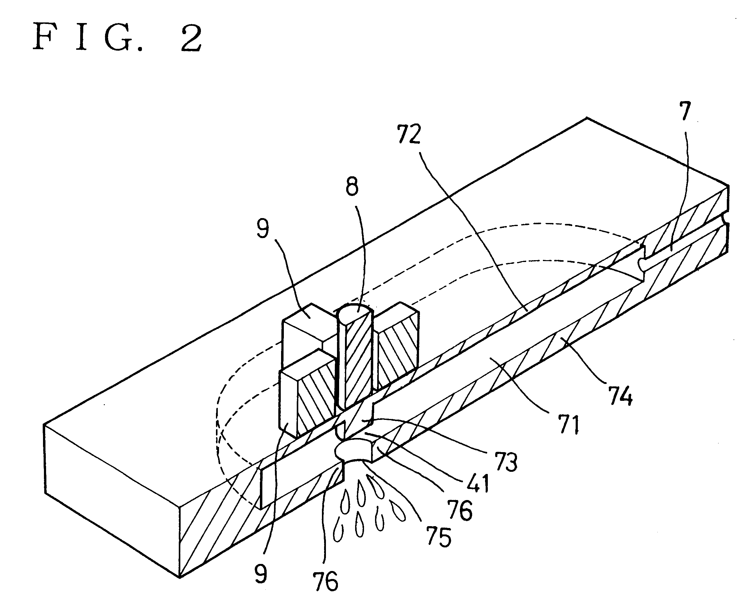
FIG. 1 is an end elevation view in which the liquid-drop discharge device is longitudinally cut along its center, and FIG. 2 is an explanatory view showing FIG. 1 in a diagonal manner.

The liquid-drop discharge device 1 is comprised of a float cell 2 provided with a valve 6 and communicating to a liquid storage tank, a liquid discharge means 4 for discharging liquid within the float cell 2, and a reaction cell 3 provided with a space into which fluid is discharged from the liquid discharge means 4 for collecting the discharged fluid. Air is being supplied to the reaction cell 3 for collecting liquid or minute particles, and an internal pressure P1 of the liquid storage tank or the float cell 2 and an internal pressure P3 of the reaction cell 3 are set such that a relationship of P1=P3, in which the pressures are identical to atmospheric pressure, or P1>P3 to supply ...


PUM


Abstract

A liquid-drop discharge device is provided including a float cell provided with a valve and communicating to a liquid storage tank, a liquid discharge mechanism for discharging liquid within the float cell, and a reaction cell provided with a space into which fluid is discharged from the liquid discharge mechanism for collecting the discharged fluid. Air is supplied to the reaction cell for collecting liquid or minute particles, and an internal pressure P1 of the liquid storage tank or the float cell and an internal pressure P3 of the reaction cell are set such that a relationship of P1=P3, in which the pressures are identical to atmospheric pressure, or P1>P3, to supply stronger air, is satisfied.

Description

BACKGROUND OF THE INVENTION1. Field of the InventionThe present invention relates to a liquid-drop discharge device used in various machineries for processing liquid by performing discharge of liquid.2. Description of the Prior ArtInk jet discharge devices as disclosed, for instance, in Japanese Patent Unexamined Publication No. 6-40030 (1994) are conventionally known types of devices for discharging liquid in form of minute particles used in particular fields. However, such discharge devices are used in offices or schools under relatively stationary conditions with little fluctuations in temperature or pressure of peripheral environments when being used, and are not exposed to significant fluctuations in operating environments.On the other hand, minute powders of various chemicals are being used as auxiliary products for manufacturing semiconductors or the like, wherein the required standards in view of particle size can not be achieved by simply using mechanical crushing means, an...

Claims


Application Information

Patent Timeline
IPC IPC(8): B41J2/02B41J2/015B05B17/06B05C5/00B41J2/215
CPCB41J2/02
Inventor HIROTA, TOSHIKAZUOHNISHI, TAKAOTAKEUCHI, YUKIHISA
Owner NGK INSULATORS LTD
Learn More