
Method for producing yarn and apparatus thereof

A yarn manufacturing and yarn technology, applied in the field of yarn manufacturing and its devices

Inactive Publication Date: 2005-04-27
INVISTA TECHNOLOG IES S A R L
View PDF5 Cites 4 Cited by
  • Summary
  • Abstract
  • Description
  • Claims
  • Application Information

AI Technical Summary

Problems solved by technology

None of these patents teach the use of air shields in conjunction with tension doors

Method used

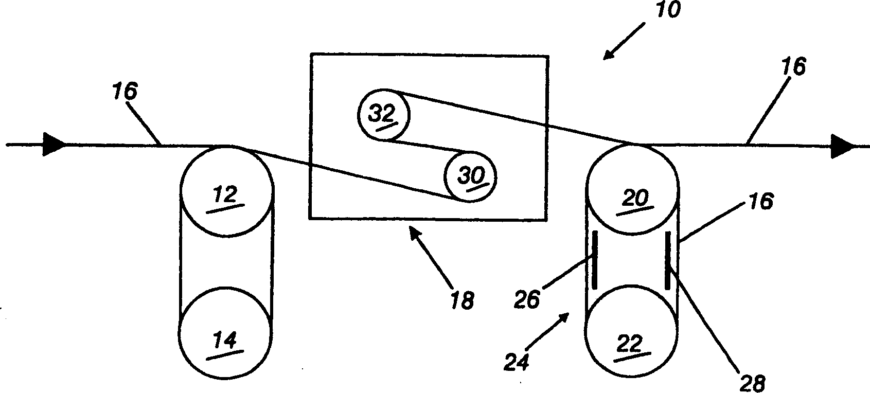
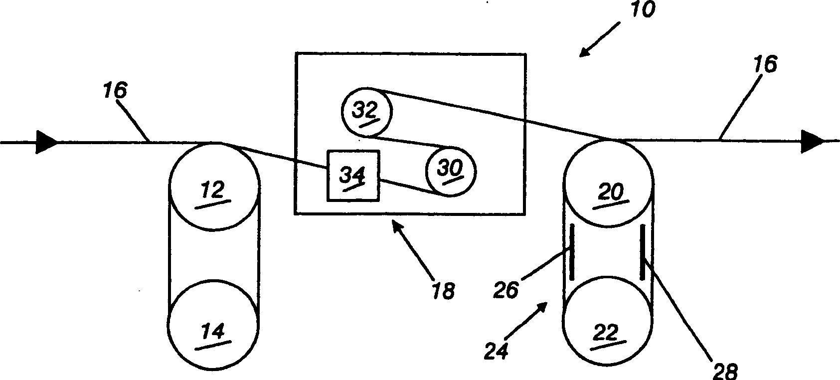
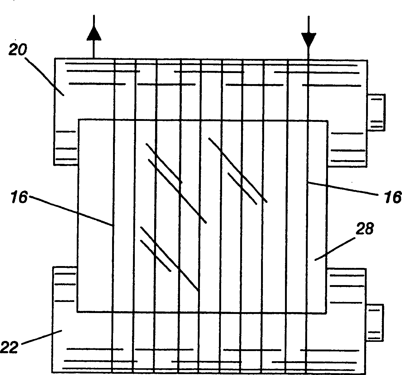

Image

  • Method for producing yarn and apparatus thereof
  • Method for producing yarn and apparatus thereof
  • Method for producing yarn and apparatus thereof

Examples


example 2

[0048] Using the configuration of Example 1, Test 4, an additional tension gate is added before the two roller tension gates, such as figure 2 shown. The tension gate is an air intermingler operating at a pressure of 30 psig. Using a draw speed of 5000 mpm, the relaxation rate on the relax roll was 8.91% at a temperature of 150°C (draw roll held at 242°C).

[0049] At 5,000 mpm, the spinning stability improved from 3.0 to 2.75 when air was supplied to the mixing element.


PUM


Abstract

The present invention relates to the combination of a tension gate and an air shield in the relax zone of a fiber production process. The combination provides a synergistic effect over an air shield alone, or a tension gate alone, or the added effect of both a tension gate and an air shield. The air shield is a plate like structure with or without perforations. The air shield plates are placed in close proximity to a pair of rolls following the tension gate. The tension gate can be one or more air drag devices, one or more liquid drag devices, or one or more solid surface contact devices, or a combination of any of the above. The apparatus and the process for using the apparatus is disclosed and claimed.

Description

technical field [0001] The present invention relates to a synergistic combination of an air shield and a tension gate arrangement and a method of operating the synergistic combination in a slack zone during yarn manufacture. Air shields and tension gate devices are included in the relaxation zone during yarn manufacturing to increase yarn stability on the relaxation rolls, especially at process speeds greater than 4,000 m / min Down. In particular, the invention relates to the part of yarn manufacture in which the yarn is relaxed to control its shrinkage without reducing the stability of the yarn on the relaxation rolls. Typical methods with means for relaxing the yarn during manufacture are spin-draw, draw-twist, draw-twist, draw-bulk methods. Background technique [0002] It is known to use air shields in the relaxation phase of yarn manufacture. It is also known to use tension gates in the relaxation zone. [0003] US Patent 5,240,667 to Andrews, Jr. et al. discloses a ...

Claims


Application Information

Patent Timeline
IPC IPC(8): D01D5/16D01D10/00D02G1/16D02G1/20D02J1/08D02J1/22
CPCD02J1/22D02J1/08D02G1/168D01D5/16D02G1/20D01D7/00D01D10/00D01D10/04
Inventor 马赫·A·德贝内迪克蒂斯
Owner INVISTA TECHNOLOG IES S A R L
Learn More