
Connector with floating structure

A technology of connector and structure, which is applied to the installation of connecting parts, devices to prevent wrong connection, protective clothing, etc., can solve the problems of deformation or twisting of flexible cable 19, inability to fully absorb the cone surface, and inability to contact the cone surface, etc. To achieve the effect of preventing breakage or poor connection

Inactive Publication Date: 2005-05-04
SMK CO LTD
View PDF1 Cites 6 Cited by
  • Summary
  • Abstract
  • Description
  • Claims
  • Application Information

AI Technical Summary

Problems solved by technology

[0007] Although the floating structure of the above-mentioned connector can absorb displacement within the contact range of the tapered surfaces 16, 17, if Image 6 As shown, the connector 13 on the bracket 11 will be biased to either side of the hole 27, so only the tapered surfaces 16, 17 may not be able to fully absorb
E.g, Figure 7 In , when the connector 14 on the digital camera is shifted to the right as shown by the dotted line and combined with the connector 13 on the bracket 11, even if the combination is released, the connector 13 on the bracket 11 will still remain At this position, in this state, when the connector 14 on the digital camera is embedded toward the left side as shown by the double-dot dash line, the deviation between the connectors is the largest, so it will be caused by excessive deviation. The problem that the conical surfaces 16 and 17 cannot be in contact
In order to solve the above problems, a large tapered surface can be used, but the overall structure of the connector tends to be miniaturized, so it is difficult to use a large tapered surface
[0008] Also, if Figure 5 As shown, the connector 13 on the bracket 11 is formed on the movable base plate 23, which itself is combined with the fixed base plate 18 by the flexible cable 19, but in order to absorb errors when the connectors are combined After moving freely within a certain range, it stays in its position even if it is disengaged, thus deforming or twisting the flexible cable 19

Method used


Image

  • Connector with floating structure
  • Connector with floating structure
  • Connector with floating structure

Examples


Embodiment 1

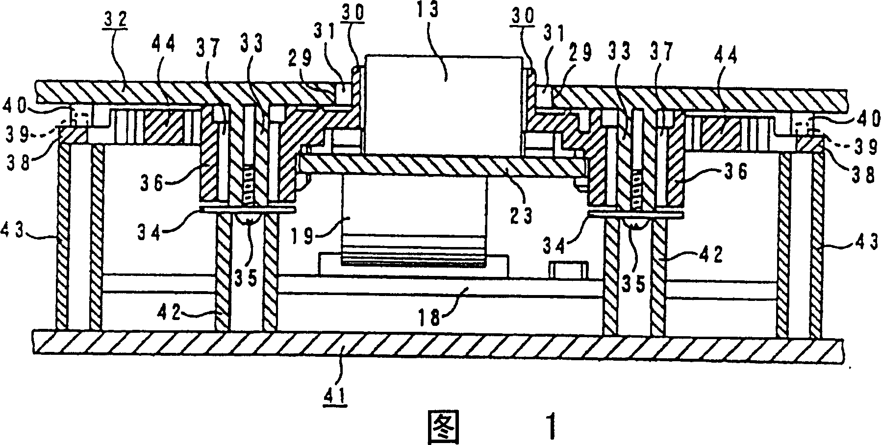
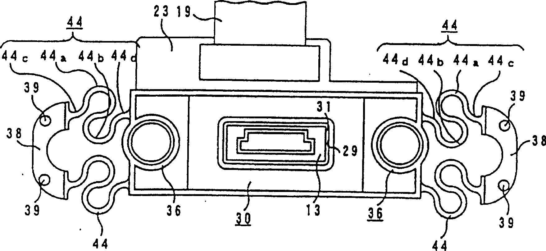
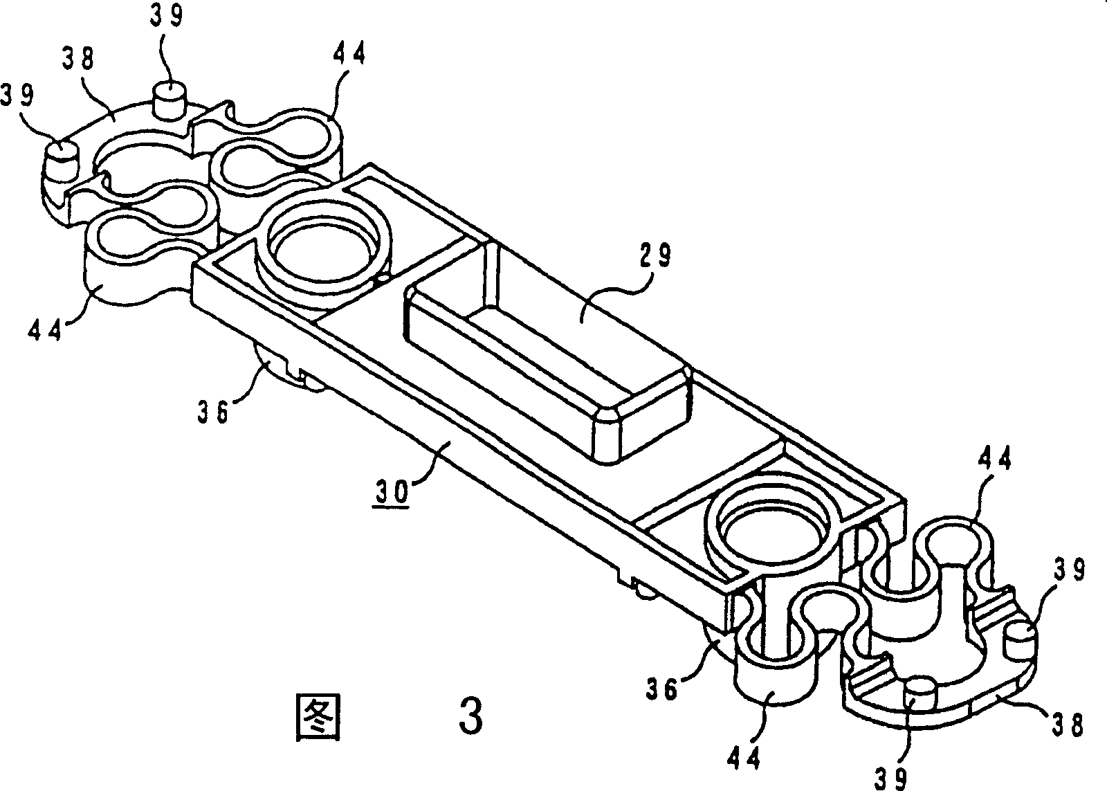
[0028] A first embodiment of the present invention will be described below with reference to FIGS. 1 to 3 .

[0029] In Fig. 1, on the housing 32 on the bracket 11, a connector setting window 29 is provided at the protruding part of the connector 13, and a window 29 is provided on the lower side of the housing 32 on both sides of the above-mentioned connector setting window 29. There is a cylindrical hub 33. A connector case 30 for protecting the connector 13 is fitted inside the connector installation window 29 , and a gap 31 is provided between the connector installation window 29 and the connector installation window 29 . The above-mentioned connector 13 is connected to a movable substrate 23 mounted on the lower side of the connector housing 30 . In addition, in the connector housing 30 , the cylindrical portion 36 having an inner diameter larger than the outer diameter of the hub 33 has a gap 37 for movably fitting the hub 33 , and the height of the cylindrical portion 36 ...

Embodiment 2

[0033] based on the following Figure 4 A second embodiment of the present invention will be described.

[0034] In the above-mentioned embodiment, the elastic S-shaped elastic portion 44 is integrally formed on the connector housing 30 as a floating structure capable of moving in all directions to return the connector 13 to the center, but the present invention is not limited to this structure. Figure 4 Shown is the structure shown in the second embodiment of the present invention, and the elastic member extending along the plugging direction of the connector is integrally formed on the connector housing 45 or the supporting housing 49 to replace the S-shaped elastic part 44, without adding The number of parts is such that the connector 13 is returned to the center.

[0035] Figure 4 Among them, on the housing 47 on the bracket, a connector setting window 48 is provided at the protruding part of the connector 13, and the connector housing 45 for protecting the connector ...


PUM


Abstract

As to the connector having a floating structure in which a movable substrate coupled with the connector is integrally fitted to a housing of the connector, a contacting part of the connector with another is made faced with a connector-setting window of a cradle housing, and the connector is structured to move freely within the range of the gap, an elastic part made of the same member as either a fixed cradle housing or the connector is formed between a fixed cradle housing side and a freely moving connector side to return the connector to an original position by returning force of the elastic member when the connector is released from linking with the other.

Description

technical field [0001] The present invention relates to a connector with a floating structure. When connecting a connector on an electrical device such as a digital camera, a mobile phone, or a digital video camera, to a connector on a bracket such as a charger, one side of the connector can be It has a degree of freedom for forward, backward, left, and right movement, and can absorb the displacement of the coupling position between the connectors. Background technique [0002] In the past, digital cameras, mobile phones, digital video cameras and other electrical equipment were connected to the cradle to send and receive information or charge with other electrical equipment. At this time, the digital camera, the mobile phone, the digital video camera and the bracket are connected to each other by connectors. E.g Figure 8 As shown, when the digital camera is placed on the cradle 11 for connection, the connector 14 on the digital camera 12 is combined with the connector 13 ...

Claims


Application Information

Patent Timeline
IPC IPC(8): H01R13/74H01R13/64
CPCA41D1/002A41D1/04A41D13/01A41D13/0525A41D2400/322
Inventor 小室雅司松田健
Owner SMK CO LTD
Learn More