Supercharge Your Innovation With Domain-Expert AI Agents!

Gate controlling circuit for raising transistor with nigh voltage input

A technology for controlling circuits and transistors, applied in logic circuits, electrical components, electronic switches, etc., to solve problems such as the inability of the input signal to be turned off by the PMOS transistor, system failure, and TDDB reliability issues.

Active Publication Date: 2005-05-11
SEMICON MFG INT (SHANGHAI) CORP +1
View PDF0 Cites 7 Cited by
  • Summary
  • Abstract
  • Description
  • Claims
  • Application Information

AI Technical Summary

Problems solved by technology

System failure may occur if the pad voltage is lower than the input threshold voltage on other die
[0004] (2) Leakage current: Because the pad voltage does not fully reach the power supply potential, there will be leakage current in other chips because the input signal cannot completely turn off the PMOS transistors in other chips
[0008] To sum up, when a high voltage signal is applied to the pad, if one cannot control the gate bias voltage of the pull-up transistor, there will be reliability problems such as TDDB, and due to the small noise tolerance cause system failure

Method used


Image

  • Gate controlling circuit for raising transistor with nigh voltage input
  • Gate controlling circuit for raising transistor with nigh voltage input
  • Gate controlling circuit for raising transistor with nigh voltage input

Examples


Embodiment Construction

[0039] Preferred embodiments according to the present invention will now be described hereinafter with reference to the accompanying drawings.

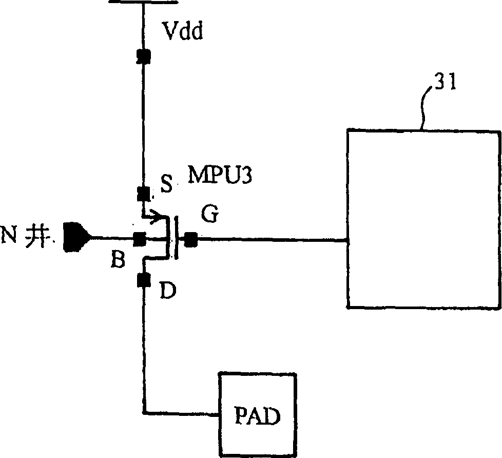
[0040] image 3 shows a schematic circuit diagram including a gate control circuit for pulling up transistors according to the present invention, in this circuit, the gate terminal (G) of the pull-up transistor MPU 3 is connected to the gate control circuit 31, and the transistor MPU 3 The source terminal (S) of the transistor MPU 3 is connected to the power supply potential (Vdd), the drain terminal (D) of the transistor MPU 3 is connected to the pad (PAD) node, and the base (B) of the transistor MPU 3 is connected to an N-well. image 3 The operation of the circuit is that when a high voltage signal is applied, the gate control circuit 31 is used to control the gate bias voltage of the pull-up transistor MPU 3, that is, the pull-up transistor is controlled by the gate control circuit 31 The gate voltage of the MPU 3 and the well bi...


PUM


Abstract

In the circuit, the gate end (G) of voltage-pulling transistor is connected with gate control circuit. The source end (S) of voltage-pulling transistor is connected with the potential of power. The drain electrode (D) of voltage-pulling transistor is connected with node of welding-sheet, and the substrate of voltage-pulling is connected with a N-well. When the high voltage signal is applied, the gate control circuit is used to control the gate bias voltage of the voltage-pulling transistor.

Description

technical field [0001] The present invention relates to a gate control circuit for pulling up transistors, in particular to a gate control circuit for pulling up transistors with high voltage input. Background technique [0002] figure 1 A known pull-up transistor circuit is schematically shown, in which the source terminal (S) and base (B) of the PMOS pull-up transistor (MPU) 1 are connected together and then connected to the supply potential Vdd, The gate terminal (G) of the transistor MPU1 is connected to Vss, and the drain terminal (D) of the transistor MPU1 is connected to the drain terminal (D) of the NMOS transistor MN1, the base (B) of the transistor MN1 is connected to Vss, and the transistor A gate terminal (G) of MN1 is connected to a power supply potential (Vdd), and a source terminal (S) of transistor MN1 is connected to a pad (PAD). exist figure 1 In the circuit, since the gate terminal (G) of the NMOS transistor MN1 is connected to the power supply potentia...

Claims


Application Information

Patent Timeline
Patent Type & Authority Applications(China)
IPC IPC(8): H03K17/00H03K17/687H03K19/00H03K19/0944
Inventor 李炳云
Owner SEMICON MFG INT (SHANGHAI) CORP
Features
  • R&D
  • Intellectual Property
  • Life Sciences
  • Materials
  • Tech Scout
  • Unparalleled Data Quality
  • Higher Quality Content
  • 60% Fewer Hallucinations
Learn More