Powder magnetic core and HF reactor therewith
A powder magnetic core, powder technology, applied in the direction of inductance with magnetic core, inductor, magnetic core/magnetic yoke, etc., can solve the problems of reduced insulation between powder particles, deterioration of frequency characteristics, increase of eddy current loss, etc., to ensure Excellent insulation and frequency characteristics
- Summary
- Abstract
- Description
- Claims
- Application Information
AI Technical Summary
Problems solved by technology
Method used
Image

Examples
Embodiment 1
[0030] Weigh and mix the required amount of silicone resin, silane-based coupling agent, MgCO 3 powder, MgO powder, using a metal mold at room temperature at 15ton / cm 2 pressure forming to obtain a dust core in the shape of a spiral tube with an outer diameter of 20 mm, an inner diameter of 10 mm, and a thickness of 5 mm. Table 1 shows the weighed composition of the above-mentioned components in this example. Here, four types of powder magnetic cores were produced as examples, and one type of powder magnetic core was produced as a comparative example.
[0031] silicone resin
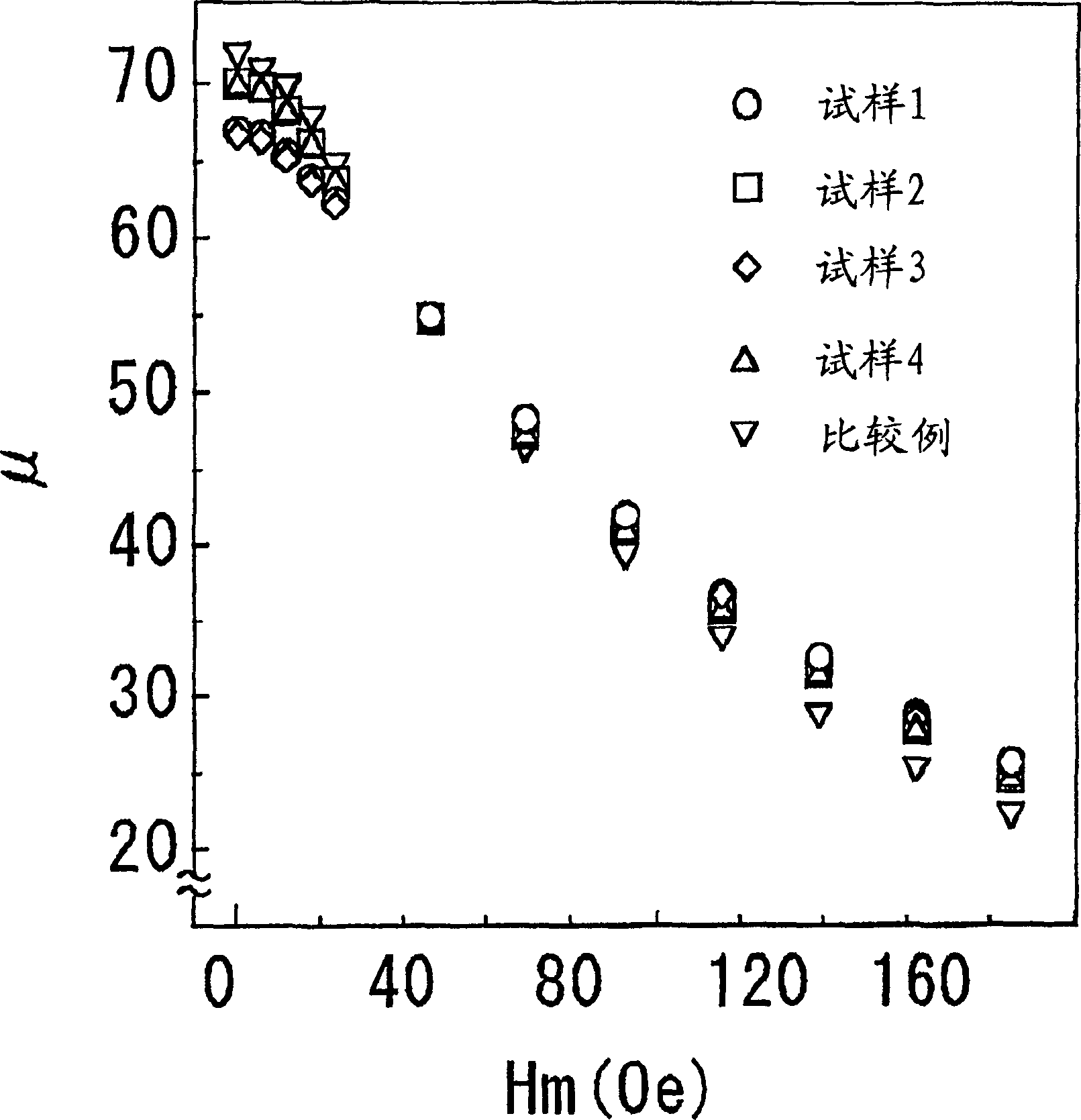
[0032] Then, the dust core was heat-treated at 800° C. for 2 hours in nitrogen to heat-treat the silicone resin and remove deformation during powder molding. Next, this dust core was housed in a case made of an insulator and wound, and the DC superposition characteristic was measured with a 4284A precision instrument manufactured by Hi-Rad Packard Co., Ltd. (hereinafter referred to as HP). ...
Embodiment 2
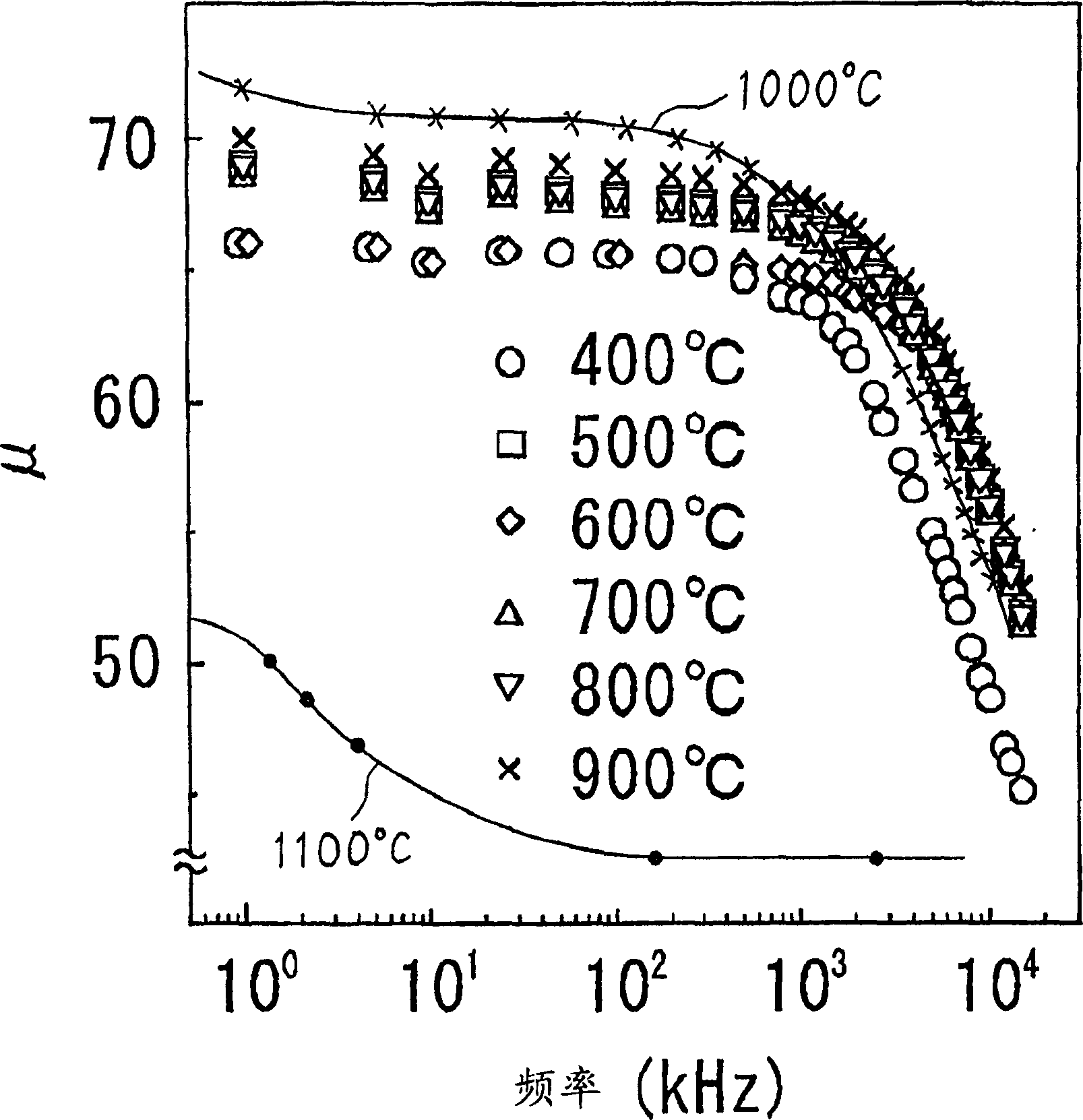
[0038] Embodiment 2 will be described below. As sample 1, the raw materials were weighed at the mixing ratio shown in sample 3 in Table 1, and the metal mold was used in the same manner as in Example 1, at room temperature at 15 ton / cm 2 pressure forming to obtain a dust core in the shape of a spiral tube with an outer diameter of 20 mm, an inner diameter of 10 mm, and a thickness of 5 mm. Then, the dust core is subjected to heat treatment in nitrogen at 400°C, 500°C, 600°C, 700°C, 800°C, 900°C, 1000°C, 1100°C for 2 hours in nitrogen, heat treatment of silicone resin and powder molding deformation removal.
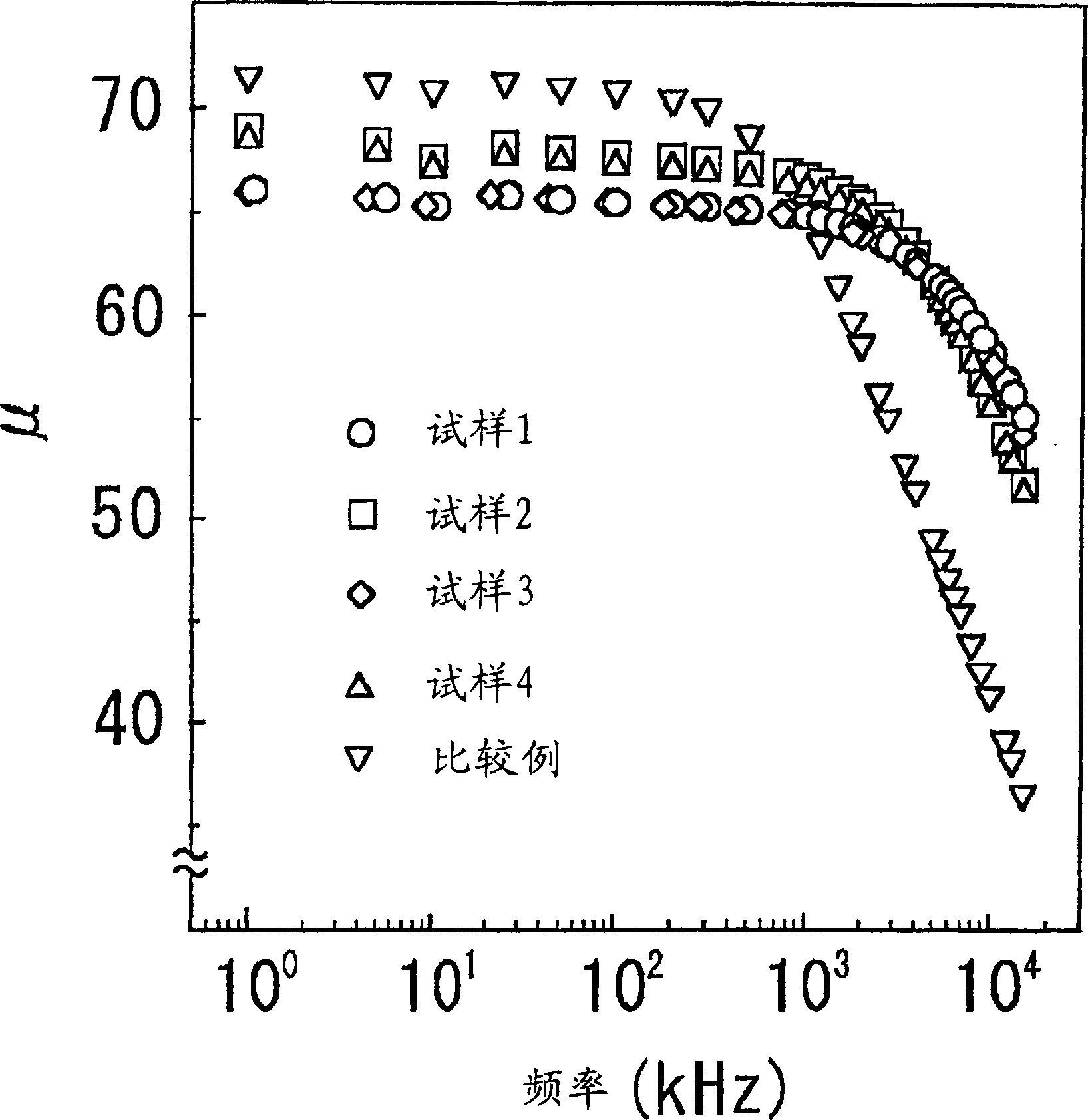
[0039] This dust core was housed in a case made of an insulator, and was wound, and the DC superposition characteristic was measured with a 4284A precision instrument made by HP. image 3 Results are shown. In addition, the frequency characteristic of μ was measured with a 4194A impedance measuring instrument manufactured by HP. Figure 4 Results are shown. From ima...
Embodiment 3
[0043] Embodiment 3 will be described below. Using 5.0% by weight of Si, 0.5% by weight of O, and the rest being Fe alloy powder used in Sample 1 of Example 1, using metal molding to form a spiral tube with an outer diameter of 50 mm, an inner diameter of 25 mm, and a height of 20 mm. Powder cores. Then, the toroidal dust core was heat-treated for deformation correction, inserted into a 5mm gap at right angles to the magnetic circuit, and wound with 60 turns of a magnetic metal wire with an outer diameter of 1.8mm to manufacture a reactor.
[0044] The inductance of this reactor 40A at the time of direct current superposition was measured and found to be 550 μH. Next, this reactor was connected to a switching power supply equipped with a very common active filter for inverter control with an output power of 2000 W class, and the circuit efficiency was measured. Here, a load resistor is connected on the output side. In addition, the circuit efficiency uses the value obtained...
PUM
| Property | Measurement | Unit |
|---|---|---|
| particle diameter | aaaaa | aaaaa |
| core loss | aaaaa | aaaaa |
| particle diameter | aaaaa | aaaaa |
Abstract
Description
Claims
Application Information