
Wireless liquid crystal display antenna

A liquid crystal display, liquid crystal display technology, applied in the direction of antenna support/installation device, instrument, identification device, etc., can solve the limitation of antenna signal reception performance, sacrifice the performance of wireless signal reception, increase complexity and product failure probability and other problems to achieve the effect of overcoming inconvenience and good receiving function

Inactive Publication Date: 2005-06-01
MITAC INT CORP
View PDF0 Cites 9 Cited by
  • Summary
  • Abstract
  • Description
  • Claims
  • Application Information

AI Technical Summary

Problems solved by technology

Although this design overcomes the above-mentioned inconvenience of configuring the antenna in an additional way, the signal receiving performance of the antenna is greatly limited, and under the commercial factors of some products that focus on appearance design, it will be more difficult because of the appearance of the product. while sacrificing the performance of wireless signal reception
[0006] Some manufacturers even integrate the antenna directly into the structure of the liquid crystal display during the production process of the liquid crystal display (for example, the Republic of China Announcement No. 490880 New Patent Case), but this product must be in the liquid crystal display process. Additional material layers such as conductive layers and transparent films are added to the film. Although this technology can achieve the effect of integrating the antenna and the LCD display, in order to add the antenna function, it is necessary to add additional layers in the original and extremely complicated LCD manufacturing process. Adding the structure of the antenna will not only increase the complexity of the whole process and the probability of product failure, but also be detrimental to the performance of wireless signal reception

Method used


Image

  • Wireless liquid crystal display antenna
  • Wireless liquid crystal display antenna
  • Wireless liquid crystal display antenna

Examples


Embodiment Construction

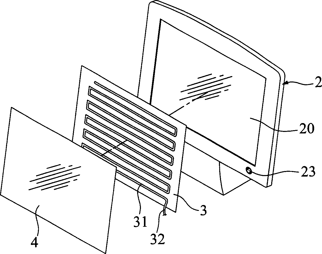
[0016] see image 3 A perspective view showing a preferred embodiment of the antenna of the wireless liquid crystal display of the present invention, it is mainly to arrange a transparent substrate 3 in front of the liquid crystal display screen 20 of the wireless liquid crystal display 2, and the transparent substrate 3 can be made of transparent materials such as glass . A wiring antenna 31 is arranged on the surface of the transparent substrate 3 , and the wiring antenna 31 can be connected to the wireless liquid crystal display 2 via a signal transmission line 32 .

[0017] One end of the signal transmission line 32 can be connected to an existing plug-in terminal (not shown) for plugging into a jack 23, so that the wireless signal received by the wired antenna 31 is sent to the wireless liquid crystal display 2 . The jack 23 can be disposed on the front panel of the wireless liquid crystal display 2 or other suitable positions.

[0018] The wired antenna 31 can be arra...


PUM


Abstract

The radio liquid crystal display (LCD) antenna has one transparent base layer set in front of the LCD screen, and the transparent base layer has distributive antenna laid on its surface. The distributive antennan is connected to one signal transmission line and radio signal receiving circuit of the radio LCD, so that the radio signal distributive antenna receives may be displayed via the display control interface on the radio LCD. The distributive antenna may be laid on the surface of the transparent base layer opposite to the LCD screen or the surface of the transparent base layer opposite to the viewer.

Description

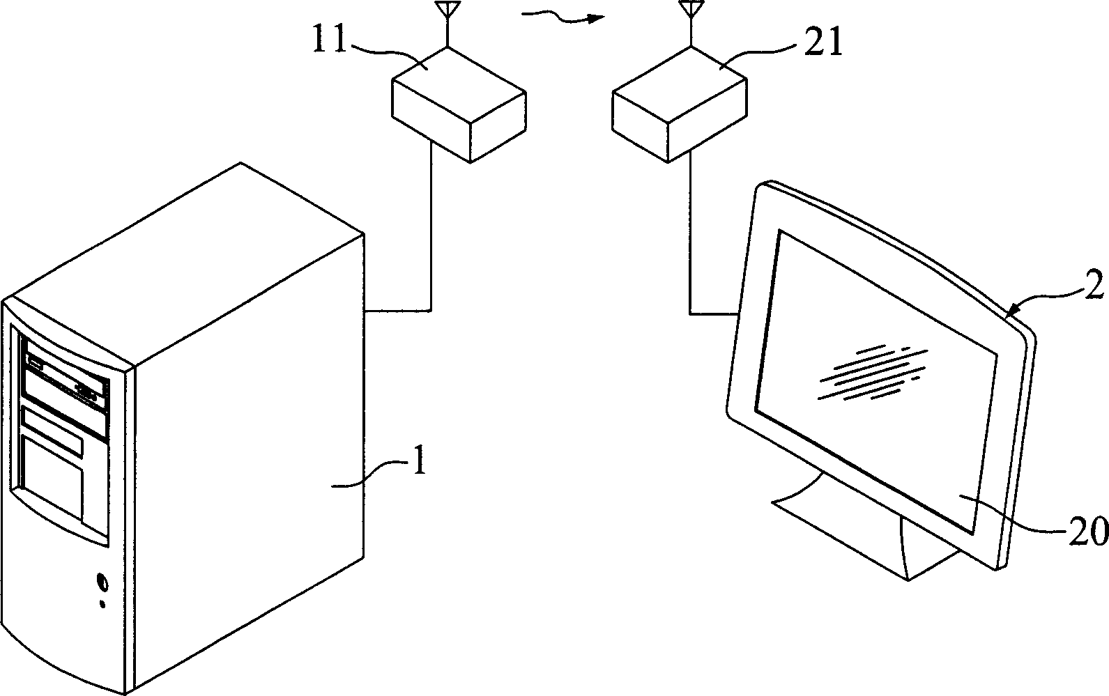
【Technical field】 [0001] The invention relates to a patch antenna for wireless signals, in particular to an antenna for a wireless liquid crystal display. 【Background technique】 [0002] A monitor is an important output device in a computer system, and the user can correctly operate the computer and obtain the output content of the computer only through the displayed content of the monitor. At present, the antennas of the wireless displays are placed on the peripheral positions in an external manner. [0003] figure 1 It is a schematic diagram showing the antenna configuration between the existing wireless liquid crystal display and the host computer, which mainly connects a wireless signal transmitting module 11 to a computer host 1, and connects a wireless signal receiving module 21 to the wireless liquid crystal display 2 . The text or graphic display signal generated by the host computer 1 can be displayed by the wireless liquid crystal display 2 through the transmiss...

Claims


Application Information

Patent Timeline
Patent Type & Authority Applications(China)
IPC IPC(8): G09F9/35H01Q1/22
Inventor 杨志祥
Owner MITAC INT CORP
Learn More