Component part in cavity die body for filling concrete

A cavity mold and component technology, which is applied to building components, building structures, floor slabs, etc., can solve the problems of high cost, low production efficiency, inconvenient production, etc.

Active Publication Date: 2005-06-15
湖南邱则有专利战略策划有限公司
View PDF2 Cites 7 Cited by
  • Summary
  • Abstract
  • Description
  • Claims
  • Application Information

AI Technical Summary

Problems solved by technology

However, this formwork component is inconvenient to manufacture, low in production efficiency, inconvenient for assembly line

Method used


Image

  • Component part in cavity die body for filling concrete
  • Component part in cavity die body for filling concrete
  • Component part in cavity die body for filling concrete

Examples


Embodiment Construction

[0061] The present invention will be further described below in conjunction with the accompanying drawings and embodiments.

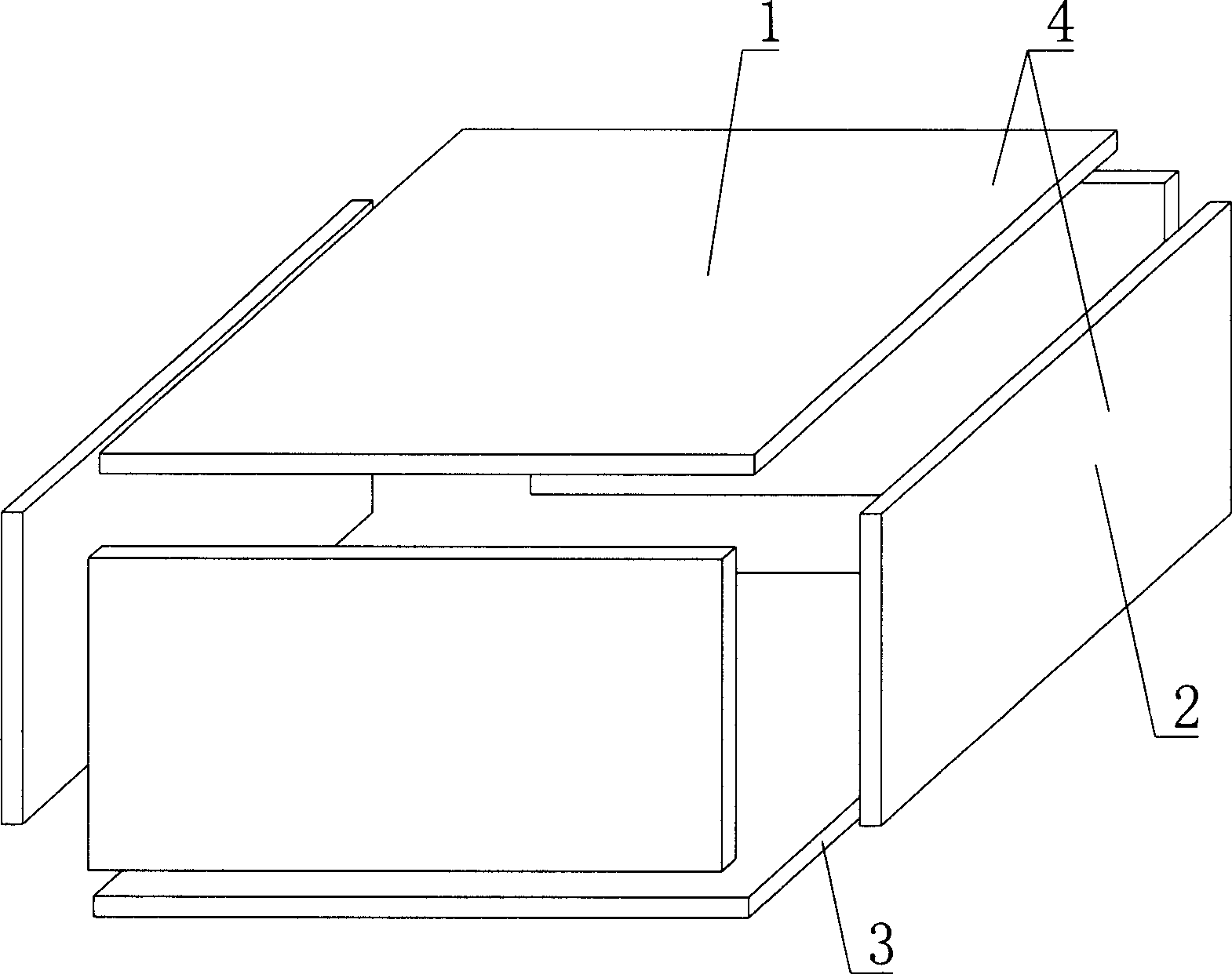
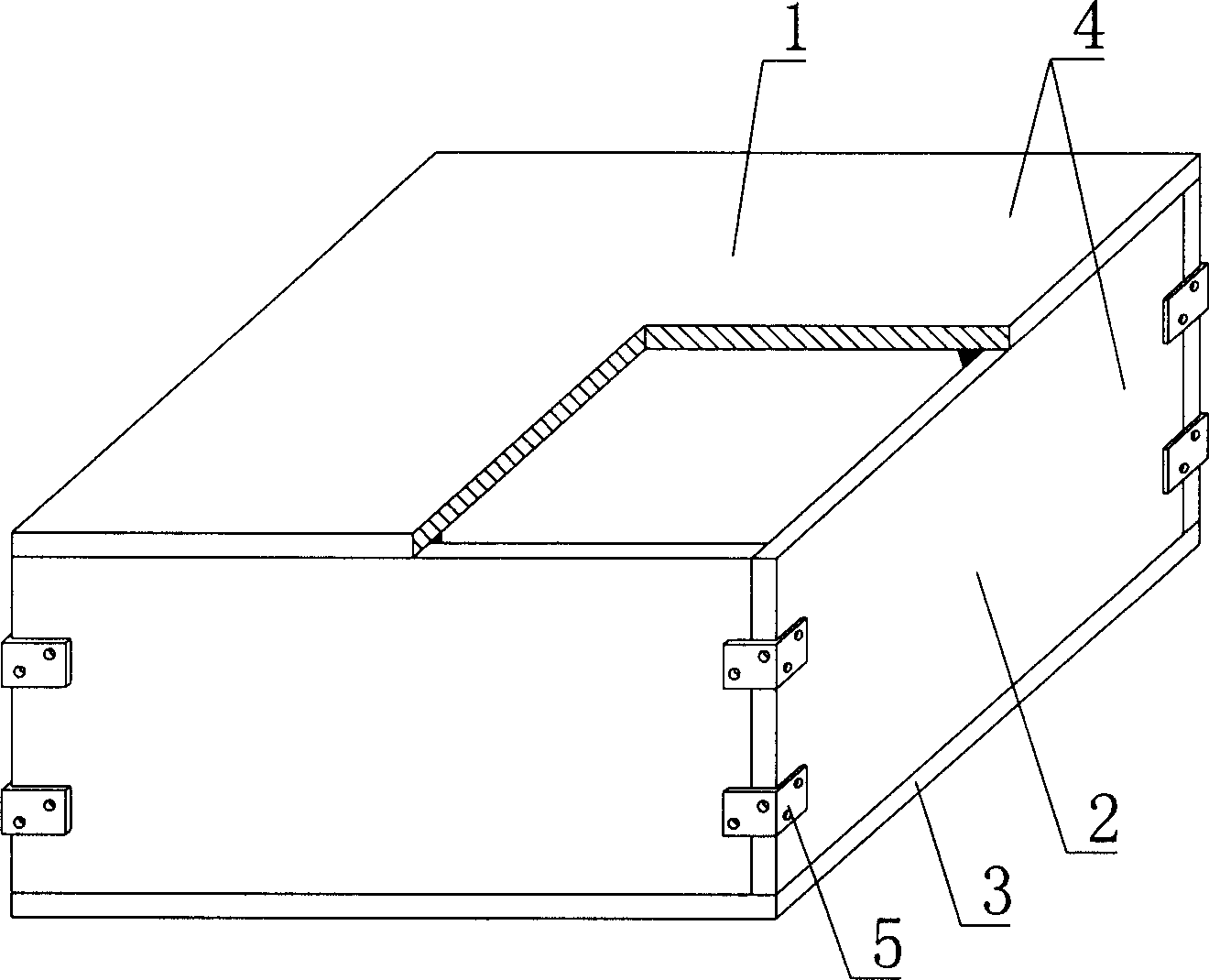
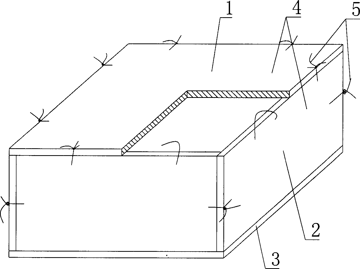
[0062] As shown in the accompanying drawings, the present invention includes an upper plate 1, surrounding side walls 2, and a lower plate 3, and the upper plate 1, surrounding side walls 2, and lower plate 3 form a closed cavity formwork, which is characterized in that the closed cavity The cavity formwork is all assembled by prefabricated components, and the prefabricated components are at least two prefabricated plates 4 . figure 1 It is a structural schematic diagram of Embodiment 1 of the present invention. In each accompanying drawing, 1 is an upper plate, 2 is a surrounding side wall, 3 is a lower plate, and 4 is a prefabricated plate. In the following accompanying drawings, those with the same number have the same description. Such as figure 1 As shown, the upper plate 1, the surrounding side walls 2, and the lower plate 3 form a closed cavity...


PUM


Abstract

The invention relates to a concrete infilling hollow cavity form member, including upper plate, peripheral side wall and lower plate. Said upper plate, peripheral side wall and lower plate can be combined together and formed into a closed hollow cavity form. It is characterized by that the described closed hollow cavity form is made up by using prefabricated components completely and adopting a splice process, and said prefabricated component includes at least two prefabricated plates.

Description

(1) Technical field [0001] The invention relates to a cavity formwork component for concrete filling. (2) Background technology [0002] At present, the cast-in-place concrete hollow floor is a widely used floor structure, and the lightweight permanent tire mold filled in it includes hollow tubes and cavity formwork components. For example, the patent No. ZL99249798.1, which the applicant applied for on November 29, 1999, is a utility model patent named "fiber-reinforced thin-walled member for reinforced concrete filling", which discloses a thin-walled formwork member, including an upper plate, The surrounding side walls, the lower bottom, and the upper plate, the surrounding side walls and the lower bottom form a polyhedral cavity. Another example is that the application number applied by the applicant on November 23, 2001 is 01140106.0, the publication number is CN1356442, and the name is called "a kind of cavity structure formwork for cast-in-place reinforced concrete fl...

Claims


Application Information

Patent Timeline
IPC IPC(8): E04B5/17
Inventor 邱则有
Owner 湖南邱则有专利战略策划有限公司
Why Eureka
Try Eureka