
Communication device

A technology for communication equipment and input data, which is applied in water lifesaving, ship safety, transmission system, etc., can solve the problem of different transmission waveforms, and achieve the effect of reducing the probability of alternating changes

Inactive Publication Date: 2005-06-15
PANASONIC CORP
View PDF1 Cites 3 Cited by
  • Summary
  • Abstract
  • Description
  • Claims
  • Application Information

AI Technical Summary

Problems solved by technology

Therefore, the transmission waveform shown in Figure 16B is not preferable compared to the transmission waveforms shown in Figures 15 and 16A

Method used


Image

  • Communication device
  • Communication device
  • Communication device

Examples


Embodiment Construction

[0047] An embodiment of the present invention is described below. In FIG. 1, the communication device 12 of the present embodiment includes an S / P converter 120, a timing detector 130, a selector 140, an encoder 106, a digital filter 108, a D / A converter 110, and a low-pass filter 112. , and a differential driver 114 . Please note that in FIG. 1 the same components as those of the communication system shown in FIG. 10 are provided with the same reference numbers and will not be described here.

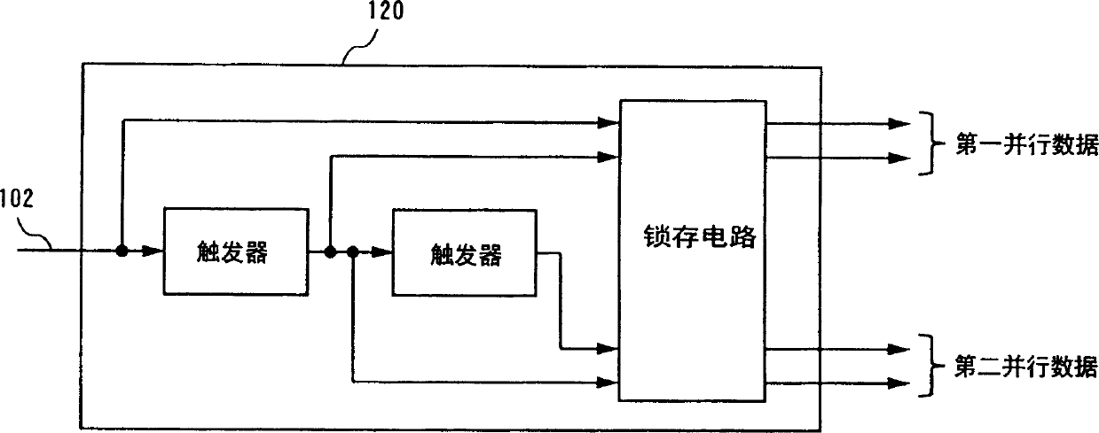
[0048] As in FIG. 10 , input data (biphase-encoded serial data) constituted by S / PDIF frames is supplied to the communication device 12 . The S / P converter 120 converts this serial data from serial to parallel every two bits at different timings, thereby outputting two kinds of parallel data.

[0049] FIG. 2 shows the structure of the S / P converter 120 . The S / P converter 120 includes two flip-flop circuits and a latch circuit for outputting two kinds of parallel data converted from...


PUM


Abstract

A communication device for transmitting input data comprising at least one biphase encoded data portion, comprising: an S / P converter (120), a timing detector (130), a transformation unit and a D / A converter (110). The S / P converter (120) converts input data from serial to parallel at every two bits at different timings, thereby outputting two kinds of parallel data. According to the input data, a timing detector (130) detects a timing corresponding to a boundary between bits of a data portion before bi-phase encoding. The selector (140) selects either one of the two parallel data output from the S / P converter (120) according to the detection result of the timing detector.

Description

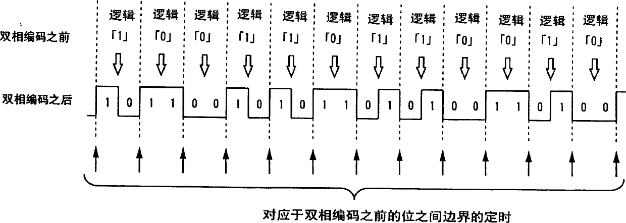
technical field [0001] The present invention relates to a communication device, and more particularly to a communication device for transmitting input data comprising at least one biphase encoded portion using an analog signal. Background technique [0002] Traditionally, to transfer digital audio data between two devices, bi-phase encoding is often used. An example of bi-phase encoding is defined in the Sony / Philips Digital Interface (S / PDIF) format. As shown in FIG. 6, in bi-phase encoding, each bit of original data is represented by two logical values. After biphase encoding, a raw data logic value of "1" indicates a state transition (such as 0 to 1, or 1 to 0) that occurs at the midpoint of a bit period, while a raw data logic value of "0" indicates a state transition at the midpoint There are no state transitions (eg, 0 to 0 or 1 to 1). Also, at the boundaries between the original data bits, the logical value is always changed (i.e., after bi-phase encoding, if the p...

Claims


Application Information

Patent Timeline
Patent Type & Authority Applications(China)
IPC IPC(8): H04L25/32H03M5/12H03M5/20H03M7/12H04L25/49
CPCH03M5/12H03M5/20H04L25/4904B63C9/13B63C9/18B63C2009/131
Inventor 堺贵久水口裕二梅井俊智胜田升
Owner PANASONIC CORP
Learn More