Impact extrusion formed article, impact extrusion forming method, and impact extrusion forming device
A stamping forming and stamping die technology, applied in the field of stamping and forming equipment, can solve problems such as affecting the appearance of products 3
- Summary
- Abstract
- Description
- Claims
- Application Information
AI Technical Summary
Problems solved by technology
Method used
Image
Examples
no. 1 example
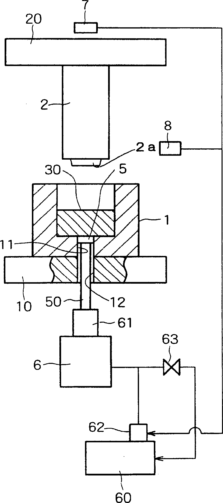
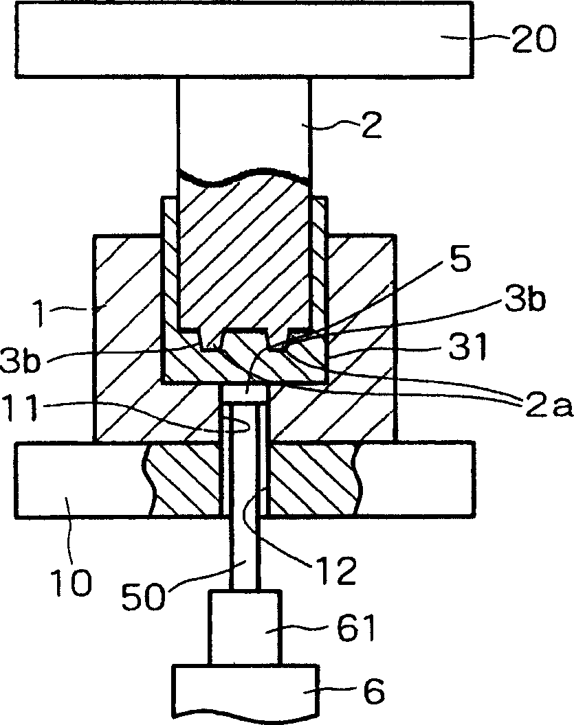
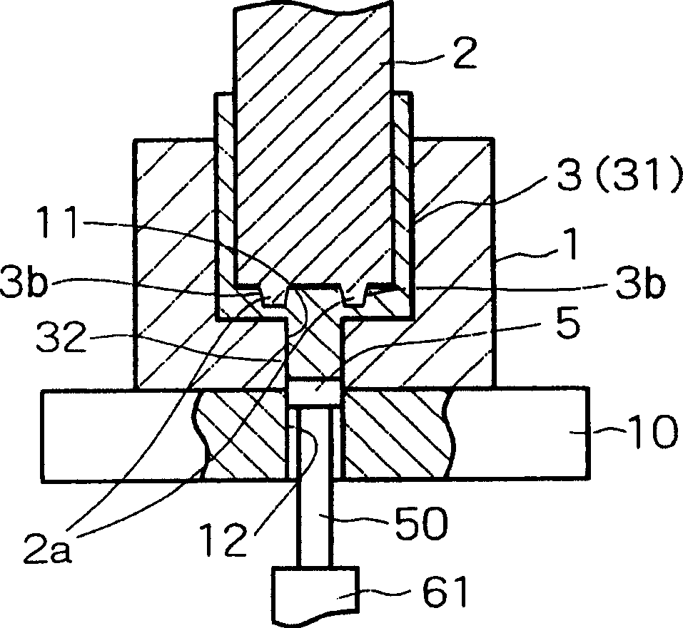
[0047] figure 1 is a schematic partial sectional view showing a first embodiment of the press forming apparatus according to the present invention. figure 2 and 3 is shown in the figure 1 A partial cross-sectional schematic view of an extrusion-molded semi-finished product of the apparatus in the first embodiment shown in . Figure 4 yes image 3 An enlarged cross-sectional schematic view of the tip portion of the punch shown in . Figure 5 is a sectional view of an extrusion molded product.
[0048] figure 1 Among them, similar to conventional equipment, the die 1 and the punch 2 are attached to the die holder 10 and the punch holder 20, respectively.
[0049] Openings 11 and 12 having the same diameter and communicating with each other are formed to penetrate the bottom of the mold 1 and the bottom of the mold holder 10, respectively. A push rod 50 is provided to slide in these openings 11 and 12 and an opening / closing device 5 is provided at the top end of the pu...
no. 2 example
[0068] Figure 6 is a partially sectional schematic view showing a second embodiment of the molding apparatus according to the present invention. The back pressure applying device 6 includes a cam having a cam shaft 64 . The other components of the molding device in the second embodiment and their functions and advantages are basically the same as those in the molding device in the first embodiment, and will not be described again here.
no. 3 example
[0070] Figure 7 is a schematic partial sectional view showing a third embodiment of the molding apparatus according to the present invention.
[0071] In the third embodiment, an appropriate number of buffer pins 22 are attached to the lower peripheral portion of the punch holder 20 . The buffer pins 22 are constructed in the following manner: when the punch 2 is lowered, the corresponding buffer pins 22 descend; the lower ends of the buffer pins 22 project downward from the guide holes 13 formed in the die holder 10 respectively; The cushion pad 65 is pushed down, thereby releasing the back pressure applied to the opening / closing device 5 . In this embodiment, there is no need for figure 1 Pressure sensor 7 and position sensor 8 are shown in.
[0072] The other components of the molding device in this embodiment and their functions and advantages are basically the same as those of the molding device in the first embodiment, and will not be described again here.
PUM
 Abstract
Description
Claims
Application Information
 - R&D
- Intellectual Property
- Life Sciences
- Materials
- Tech Scout
- Unparalleled Data Quality
- Higher Quality Content
- 60% Fewer Hallucinations
Browse by: Latest US Patents, China's latest patents, Technical Efficacy Thesaurus, Application Domain, Technology Topic, Popular Technical Reports.
© 2025 PatSnap. All rights reserved.Legal|Privacy policy|Modern Slavery Act Transparency Statement|Sitemap|About US| Contact US: help@patsnap.com


