Movable bed

一种调整台、床垫的技术,应用在床、病床、医药科学等方向,能够解决不悦、不能认为翻转床提供良好的护理等问题,达到负担减轻、抑制褥疮的产生、好看护服务的效果

Inactive Publication Date: 2005-07-13
SANYO ELECTRIC CO LTD
View PDF1 Cites 15 Cited by
  • Summary
  • Abstract
  • Description
  • Claims
  • Application Information

AI Technical Summary

Problems solved by technology

In addition to requiring a lot of strength from the caregiver, the caregiver may feel physically uncomfortable due to the caregiver's inexperience with this difficult operation, and at the same time feel uncomfortable with every operation performed at this time. psychological displeasure
[0005] So from the point of view of the care recipient, in fact, the existing flipping bed must not be considered sufficient to provide good care

Method used


Image

  • Movable bed
  • Movable bed
  • Movable bed

Examples


Embodiment 1

[0047] 1-1 The structure of the flip bed

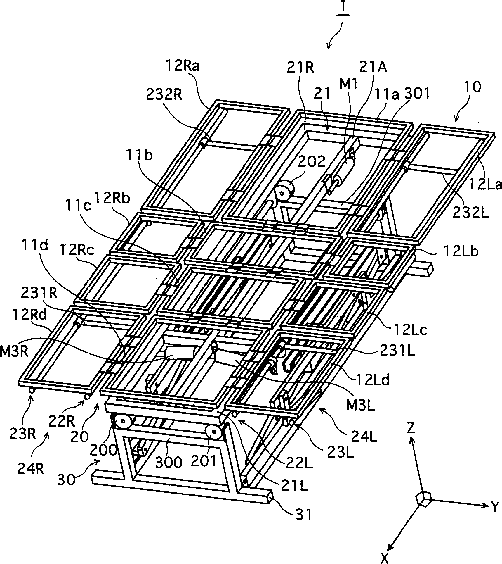
[0048] figure 1 A perspective view showing the structure of the inverted bed 1 related to Embodiment 1 of the present invention.

[0049] The structure of the reversible bed 1 is designed such that the bed frame 10 is placed on the adjustable platform 20 , and the adjustable platform 20 is placed on the fixed platform 30 .

[0050] The bed frame 10 includes connection platforms 11a to 11d, which are formed by placing the surface portion (i.e., the upper surface of the bed) corresponding to the back, buttocks, thigh and calf regions of the body of the care receiver lying on the bed. ) is divided into four articulating sections and links these sections together for full adjustment. Among the four connecting platforms 11 a - 11 d , the lower back plate 11 b is directly fixed on the adjustable table 20 , for example by welding, so as to prevent the bed frame 10 from being separated from the adjustable table 20 . The side members 12Ra-12R...

Embodiment 2

[0132] Figure 25A A perspective view of the inverted bed structure in Embodiment 2 is shown.

[0133] Although the bed structure in Embodiment 1 is driven by a parallelogram mechanism, in Embodiment 2, the direct-acting type actuator is placed vertically, and the side members on the left and right sides are vertically lifted by the lifting mechanism, which makes it possible to adjust The platform above the stage tilted.

[0134] According to the reversing bed in Embodiment 2, a pair of columnar direct-acting type actuators are provided in a rectangular fixed table, and the bed frame supported by the adjustable table is located on top of the actuators. As in Embodiment 1, the platform is designed in the form of a connecting platform connected by a plurality of joints corresponding to the upper body, buttocks, thighs, calves and other body regions of the care receiver. Wherein, the portion corresponding to the thigh plate is fixed to an adjustable frame having a frame structu...

Embodiment 3

[0138] Figures 26A to 26F The structure of the tumbling bed in Example 3 is shown.

[0139] The reversing bed in Embodiment 3 can be used for common purposes, and is formed by laying an air mattress made up of a plurality of air bags on a common bed. The tumbling bed features the use of an air pump (not shown) to inflate or deflate each air cell independently via an air hose. The air hoses are provided with valves which are controlled to be opened or closed by a control unit (not shown), thereby controlling the inflation / deflation of the respective airbags. As an example, the air cells are separated from each other into the upper body (double layer), lower back (double layer), thighs, lower legs, and sides of the bed so as to correspond to the major joints of the care receiver's body.

[0140] A flip bed having the above structure is usually used with a normal mattress or the like laid on top of an air mattress. When the care receiver turns from supine to side lying positi...


PUM


Abstract

An adjustable bed comprising: a platform having a bendable surface; a bending mechanism for bending the platform to form a bent state, the bent state including at least one of a sitting up position and a bent knee position; As well as a tilt mechanism that tilts the platform surface laterally, both the bend and tilt mechanisms are operable to operate with the other mechanisms. In addition, the adjustable bed includes: a side member disposed on a side of the platform; and a side member raising mechanism for elevating the side member relative to the platform surface, a tilt mechanism causing the platform surface to be raised toward the platform surface by the side member. The side members are tilted by the high mechanism lift.

Description

technical field [0001] The present invention relates to an adjustable bed for nursing care or the like, and in particular to an improved mechanism for reversing between the supine and side lying positions for the user of the bed, eg a care receiver. Background technique [0002] Often, adjustable beds are used as flip beds or the like for the prevention of bedsores, to assist the care receiver in changing body position, where the care receiver lies on the mattress at an angle and the care receiver is tilted by tilting at least part of the mattress. Inversion occurs (see Japanese Laid-Open Patent No. 6-14824). Most of these beds employ a mechanism that tilts the mattress from a horizontal position to one side or the other. [0003] By using the mechanism described above in an inverted bed, the care receiver's body position can be changed from lying flat on a horizontal mattress (i.e. supine) to leaning on their left or right side of their body (i.e. lying on their side). ) ...

Claims


Application Information

Patent Timeline
Patent Type & Authority Applications(China)
IPC IPC(8): A47C20/08A61G7/00A61G7/008A61G7/015A61G7/057
CPCA61G7/001A61G7/008A61G7/015A61G7/05769A61G2203/42Y10S5/942
Inventor 田口贤治阿部裕司森川雅司河上日出生小川淳
Owner SANYO ELECTRIC CO LTD
Why Eureka
Try Eureka