Wire length measuring and feeding device

A technology for feeding devices and electric wires, which is applied in the field of electric wire length measuring and feeding devices

Inactive Publication Date: 2005-08-24
JAPAN AUTOMATIC MACHINE
View PDF0 Cites 13 Cited by
  • Summary
  • Abstract
  • Description
  • Claims
  • Application Information

AI Technical Summary

Problems solved by technology

[0013] Therefore, the object of the present invention is to solve the above-mentioned problems in the prior art, and to provide an improved electric wire length measuring and feeding device, which can make the electric wire The parts of the processing unit that face each other and swing swing at a higher speed

Method used


Image

  • Wire length measuring and feeding device
  • Wire length measuring and feeding device
  • Wire length measuring and feeding device

Examples


Embodiment Construction

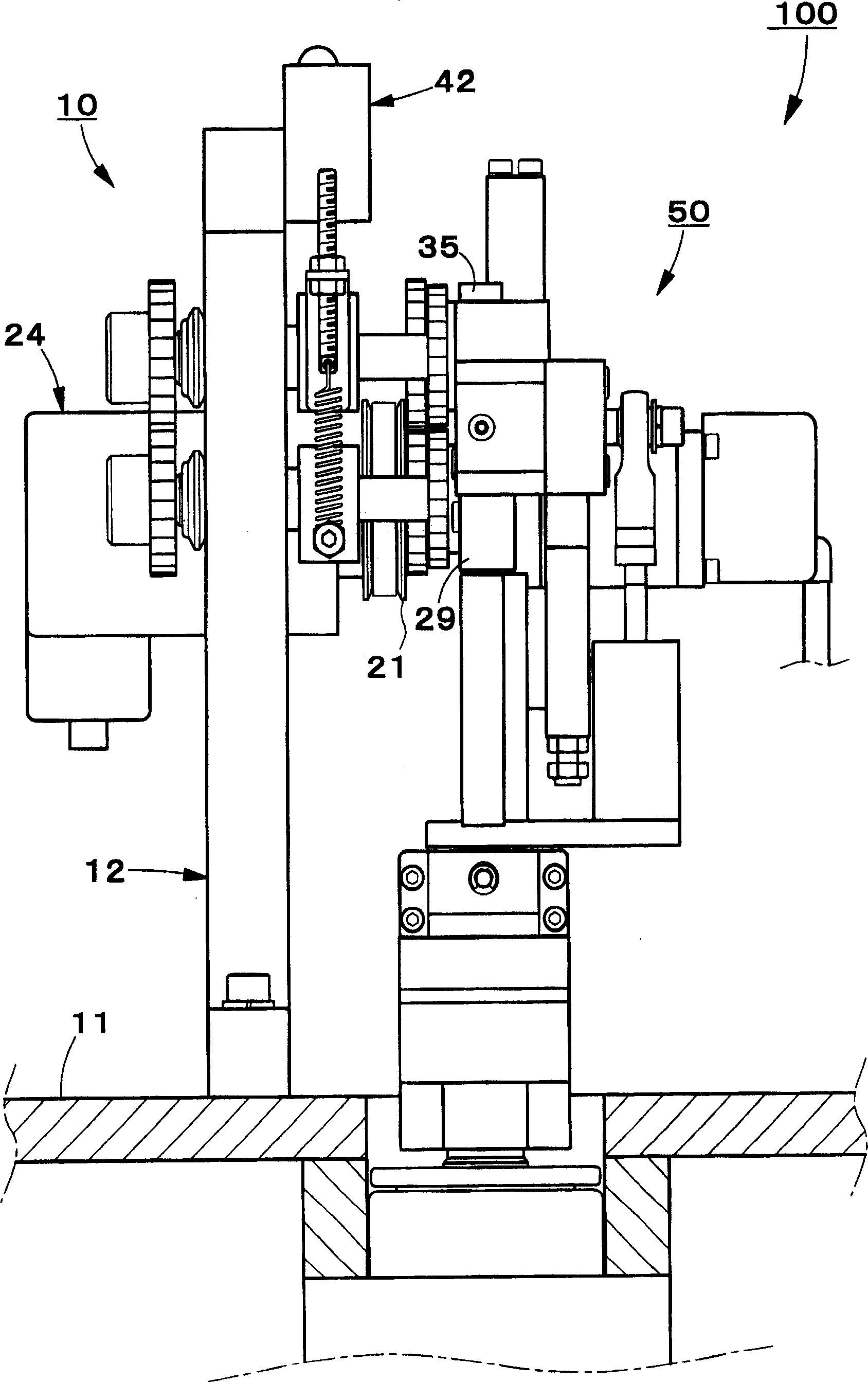
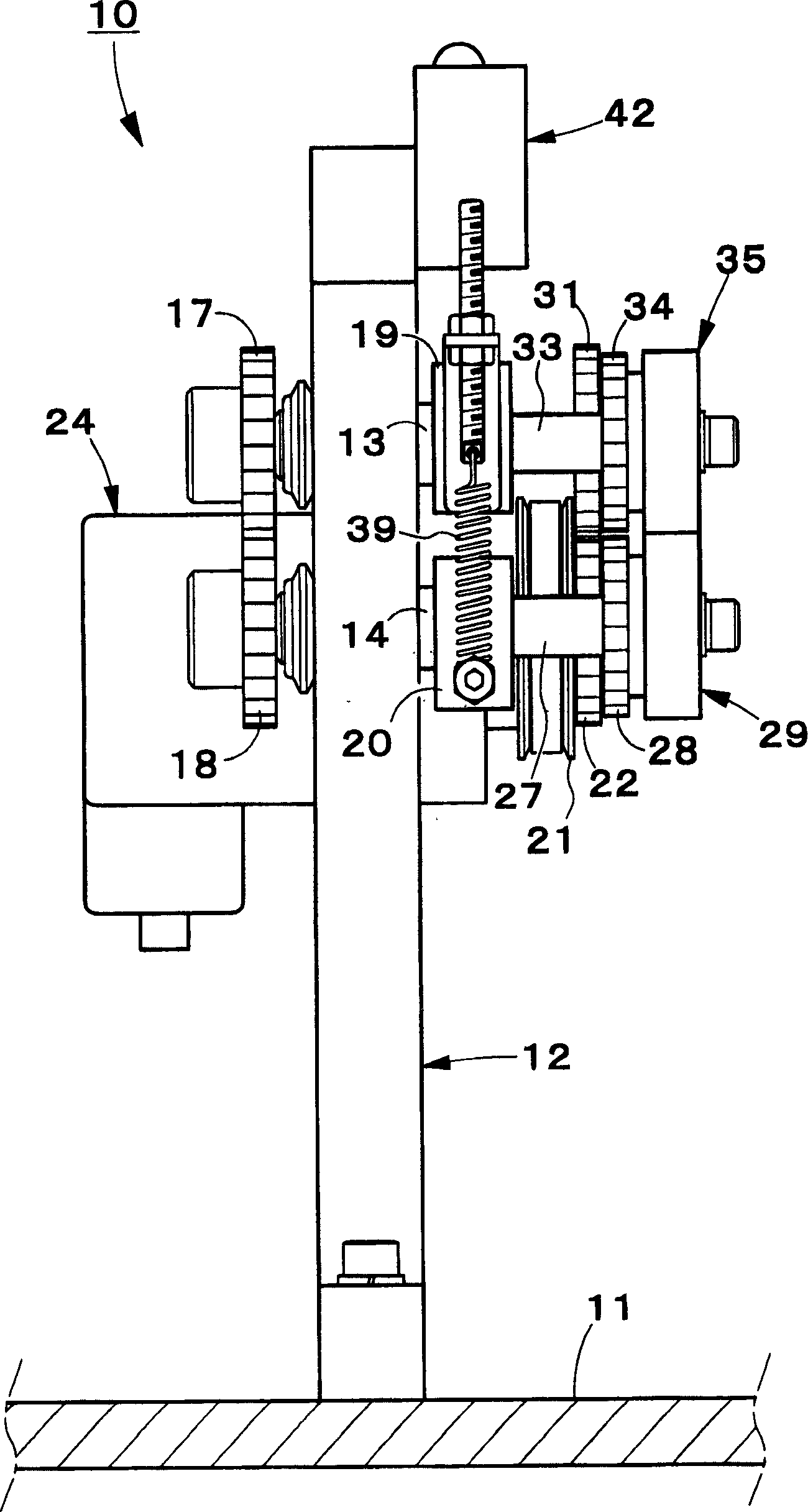
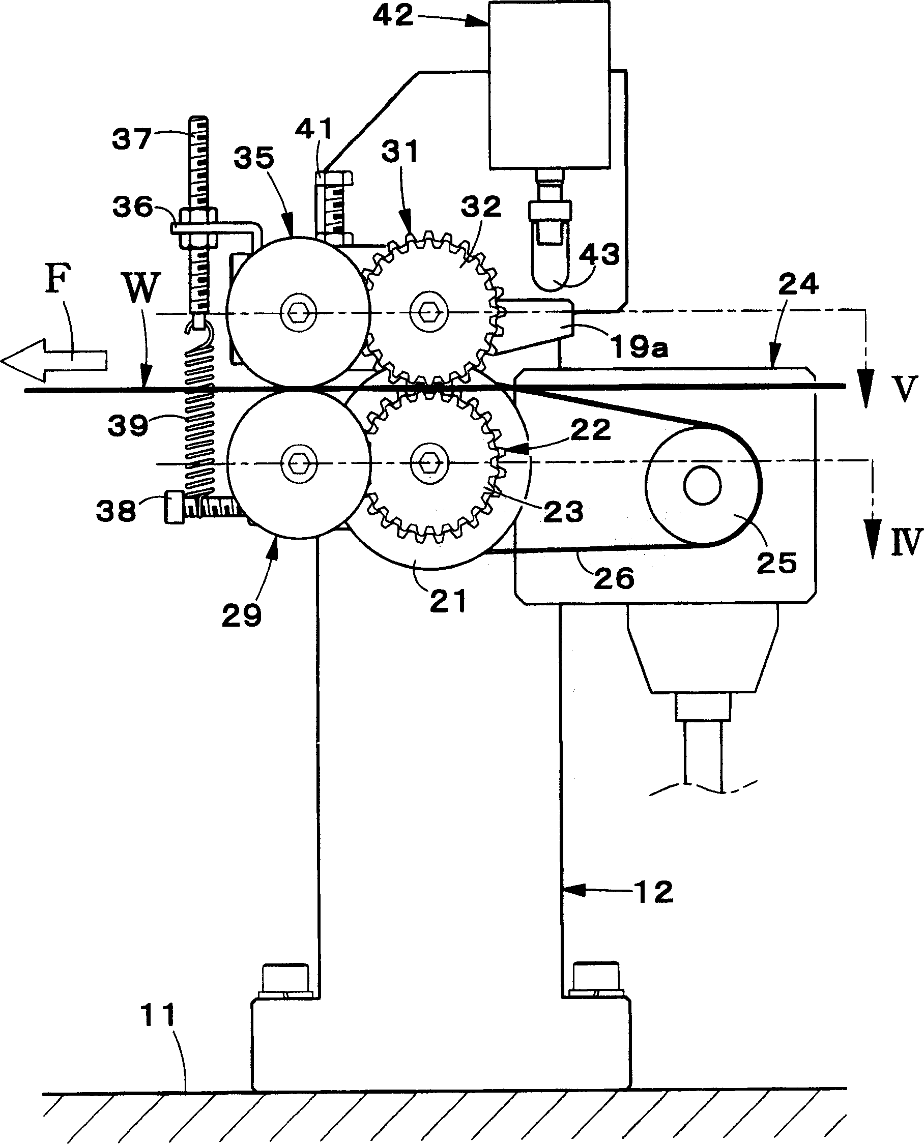
[0042] Below, refer to Figure 1 ~ Figure 1 1 An embodiment of the wire length measuring and feeding device of the present invention will be described in detail. In addition, in the following description, the direction in which the wires are fed toward the wire processing device is referred to as the front-rear direction, the vertical direction is referred to as the up-down direction, and the direction perpendicular to these directions is referred to as the left-right direction.

[0043] First, the initial reference figure 1 The wire length measuring and feeding device 100 of this embodiment is a combination of a feeding mechanism 10 fixed on a base 11 and a length measuring and swinging mechanism 50 that can swing freely on the base 11. The length measuring and swinging mechanism 50 is A structure that swings around a swing axis extending in the up and down direction.

[0044] Feeding mechanism 10 such as figure 2 -As shown in FIG. 6, it has the original plate-shaped bracket (su...


PUM


Abstract

Provided is an electric wire measuring / feeding device capable of rocking a rocking part in a higher speed without reducing overall length accuracy of an electric wire for feeding.In the electric wire measuring / feeding device 100, an electric wire feeding mechanism 10 fixed to the base is separated from an electric wire measuring / moving mechanism 50 moving on the base, so that a moving part is lightened and the moving speed can be improved. When the electric wire measuring / moving mechanism 50 lies at a first moving position, feed rollers 35 and 29 of the electric wire feeding mechanism 10 unlockably engage with a part lying on the front end side in the wire feeding direction of the electric wire W supported by the electric wire measuring / moving mechanism 50, and feed the electric wire W of a predetermined length.

Description

Technical field [0001] The present invention relates to a wire length measuring and feeding device for measuring and feeding wires toward a wire processing device. More specifically, it relates to an improved wire length measuring and feeding device that can reduce the length of the wire to be fed. When the accuracy is lowered, the part that is moved to face each part of the wire processing device is moved at a higher speed. Background technique [0002] Conventionally, a wire processing device is used to cut the wire, peel off the end coating of the cut wire to expose the core wire, and crimp the terminal on the exposed core wire (for example, , Refer to the Japanese Patent Publication No. 102354 (Heisei 8), No. 204229 (Heisei 11) and No. 261232 (2001). [0003] With reference to FIG. 13, the structure will be briefly described. The wire processing device includes: a first blade 1 that cuts the wire W; a second blade 2 that peels off the front end coating of the cut wire in the ...

Claims


Application Information

Patent Timeline
Patent Type & Authority Applications(China)
IPC IPC(8): B65H51/32B65H51/00B65H57/12B65H57/14B65H61/00B65H63/08H01R43/00H01R43/01H02G1/12
CPCB65H51/08B65H51/32B65H61/00B65H2701/341
Inventor 山田初雄黑木和彦
Owner JAPAN AUTOMATIC MACHINE
Why Eureka
Try Eureka