Electro-dynamic planar loudspeakers

A technology of electric loudspeaker and circuit, which is applied in the direction of loudspeaker shell support, loudspeaker transducer fixation, microphone, etc., and can solve the problems of high-frequency sound beam width angle or narrow coverage expected application

Inactive Publication Date: 2005-08-31
HARMAN INT IND INC
View PDF0 Cites 17 Cited by
  • Summary
  • Abstract
  • Description
  • Claims
  • Application Information

AI Technical Summary

Problems solved by technology

However, the larger rectangular size results in a high frequency beam width angle or coverage that is too narrow for its intended application

Method used


Image

  • Electro-dynamic planar loudspeakers
  • Electro-dynamic planar loudspeakers
  • Electro-dynamic planar loudspeakers

Examples


Embodiment Construction

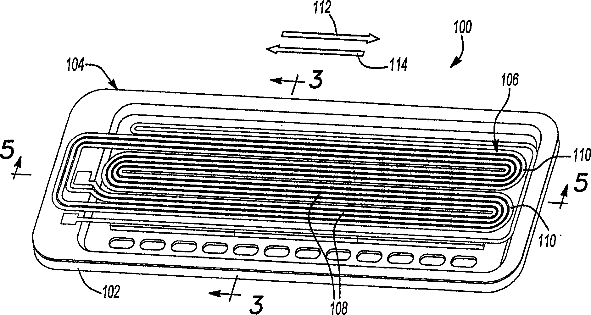
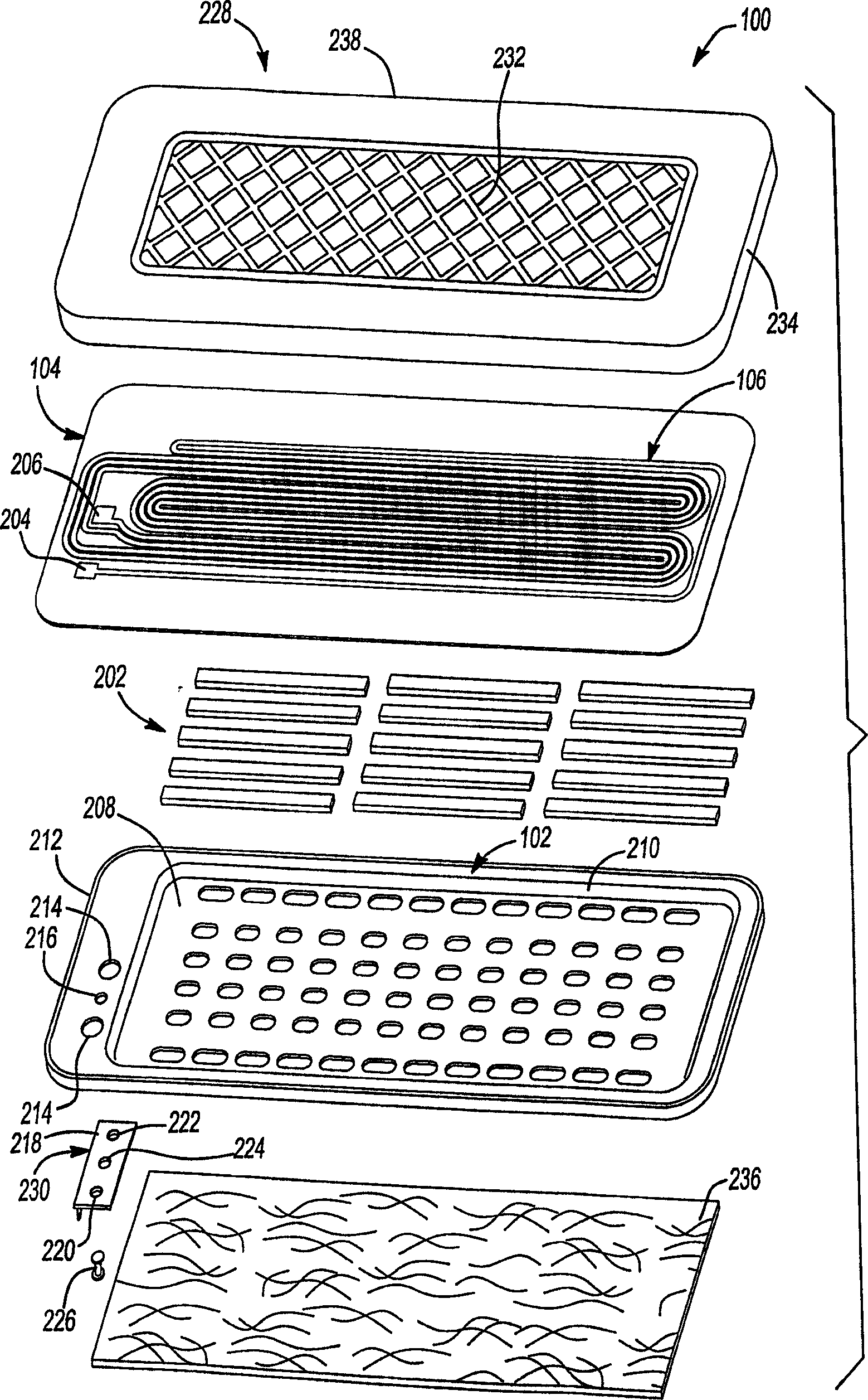
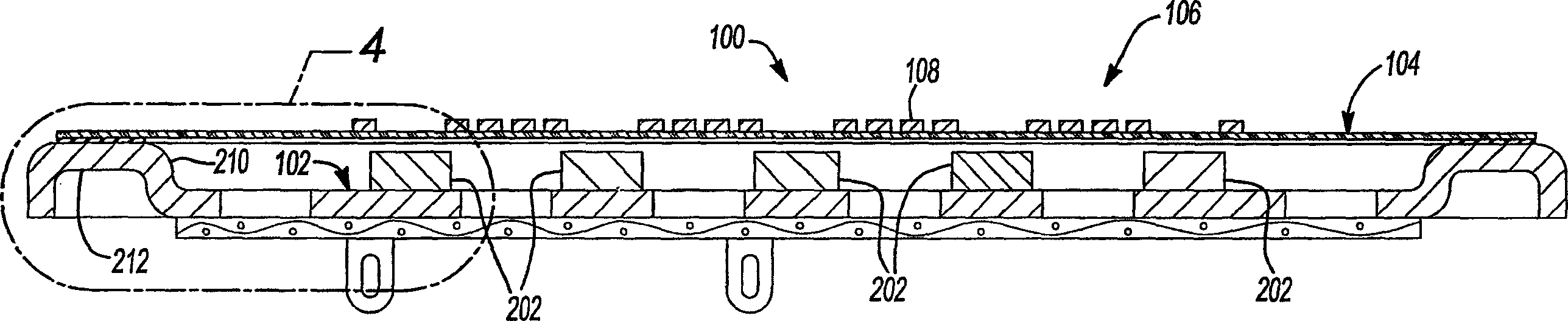
[0338] figure 1 is a perspective view of the electrodynamic planar speaker 100 of the present invention, as figure 1 As shown, the dynamic loudspeaker is basically a planar loudspeaker with a frame 102 on which a diaphragm 104 is tensioned and fixed. Diaphragm 104 is provided with a conductor 106 having a curved shape with a plurality of substantially rectilinear portions (or traces) 108 extending longitudinally along the diaphragm and interconnected by radii 110 to form a single electrical current path. Permanent magnet 202 (such as figure 2 shown) is arranged on the frame 102 under the vibrating membrane 104 to generate a magnetic field.

[0339] The straight portion 108 is disposed within the region of magnetic flux generated by the permanent magnet 202 , the straight portion 108 carries current in the first direction 112 and is disposed within the region of magnetic flux having a similarly oriented polarization. The straight portion 108 of the conductor 106 with curre...


PUM


Abstract

Electro-dynamic loudspeakers typically include a diaphragm having a conductor applied to one of its surfaces where the diaphragm is secured to a frame. The conductor is connected to a power supply for providing electrical current through linear traces of the conductor that interact with magnetic fields generated by magnets that are mounted to the frame. The diaphragm is driven by a motive force created when current passes through the conductor within the magnetic field. The electrical current is varied to create an acoustical output from the electro-dynamic loudspeaker.

Description

[0001] Cross References to Related Applications [0002] This application claims Provisional Application No. 60 / 380,001 filed May 2, 2002, Provisional Application No. 60 / 378,188 filed May 6, 2002, and Provisional Application No. 60 / 391,134 filed June 24, 2002 , and US Application No. 60 / 443,699 filed January 30, 2003 as priority. The disclosure of the above application is incorporated herein by reference. technical field [0003] The present invention relates to an electric flat speaker, and more particularly relates to an improvement of the electric flat speaker and a manufacturing method of the electric flat speaker. Background technique [0004] The conventional construction of an electrodynamic planar loudspeaker has a diaphragm in the form of a membrane attached in tension to a frame. An electrical circuit in the form of electrically conductive traces is provided on the surface of the diaphragm and a magnetic source, usually in the form of a permanent magnet, is provi...

Claims


Application Information

Patent Timeline
Patent Type & Authority Applications(China)
IPC IPC(8): H04R9/00B60R11/02H04R1/02H04R1/06H04R1/28H04R5/02H04R7/02H04R7/04H04R7/18H04R9/02H04R9/04H04R9/06H04R11/02H04R31/00
CPCH04R31/006B60R11/0217B60R11/0223B60R11/0235H04R1/025H04R1/026H04R1/06H04R7/04H04R7/18H04R9/025H04R9/047H04R9/06H04R31/003H04R2201/34H04R2400/11H04R2499/13
Inventor S・W・赫特J・F・斯蒂尔D・B・加纳R・E・芬威克L・A・曼戈SR・K・C・奥古斯丁W・N・豪斯R・米海利奇
Owner HARMAN INT IND INC
Why Eureka
Try Eureka