X-ray diagnostic apparatus

A diagnostic device, X-ray technology, applied in the direction of X-ray equipment, diagnosis, radiological diagnosis data transmission, etc.

Active Publication Date: 2005-09-07
TOSHIBA MEDICAL SYST CORP
View PDF0 Cites 7 Cited by
  • Summary
  • Abstract
  • Description
  • Claims
  • Application Information

AI Technical Summary

Problems solved by technology

[0003] The C-arm of the front system is mounted on the base with a bracket, so although it can rotate around the bracket (pillar rotation), it basically cannot move on the base surface

Method used


Image

  • X-ray diagnostic apparatus
  • X-ray diagnostic apparatus
  • X-ray diagnostic apparatus

Examples


Embodiment Construction

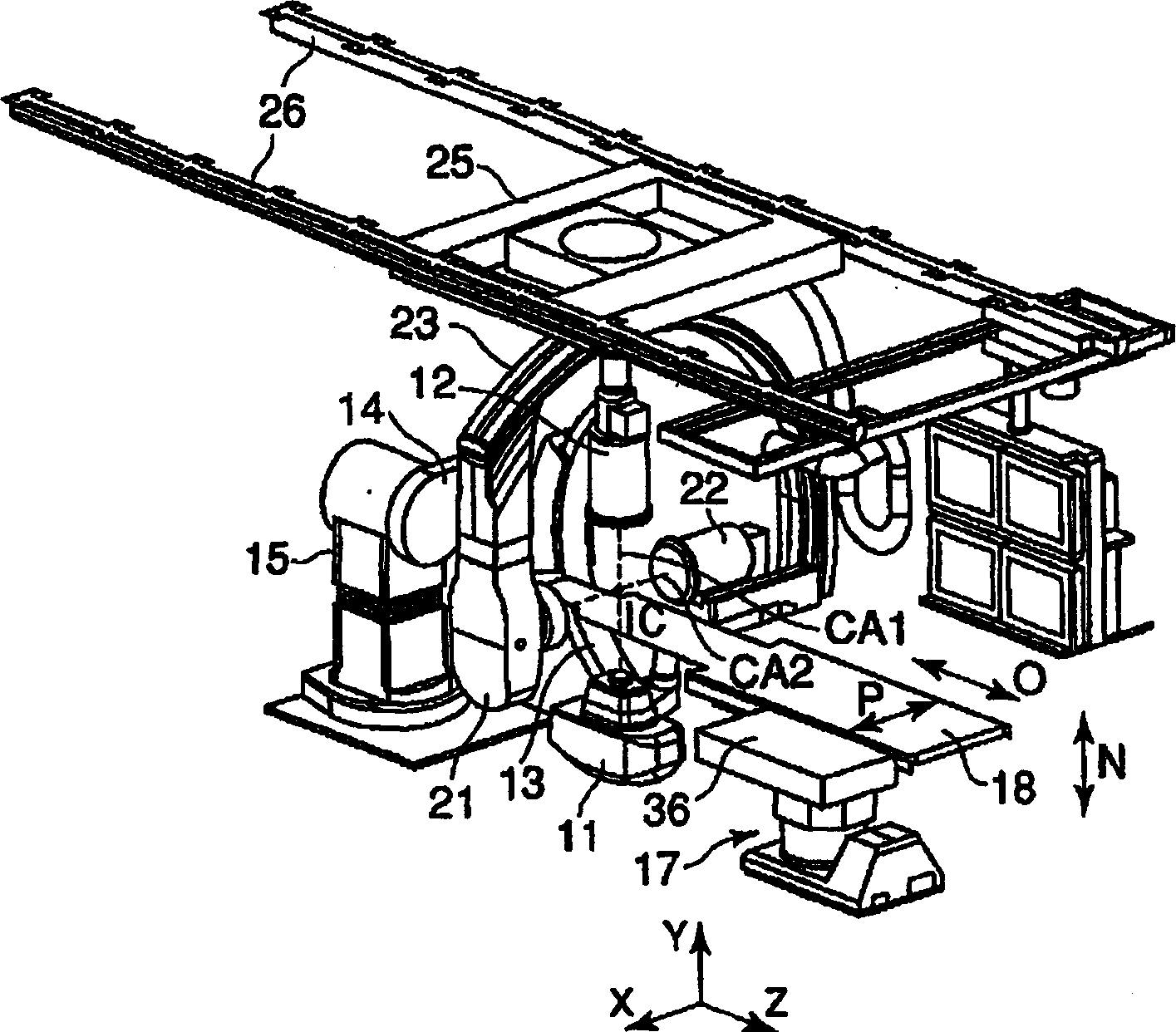
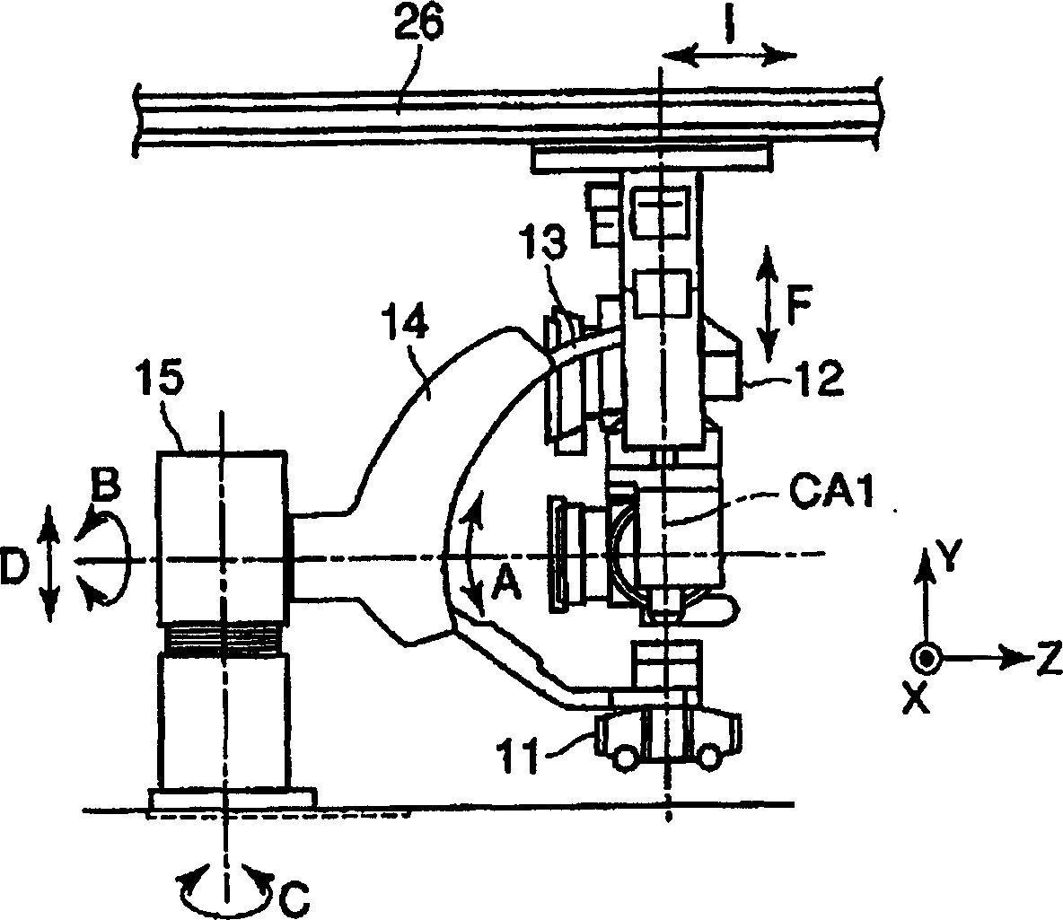
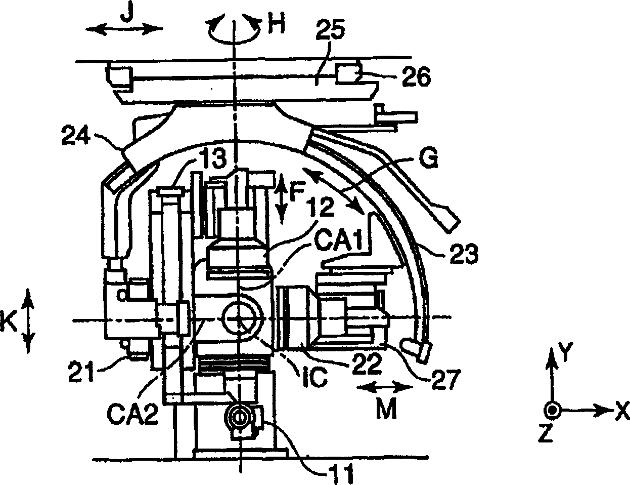
[0017] Hereinafter, an X-ray diagnostic apparatus to which the present invention is applied will be described with reference to the accompanying drawings. figure 1 The appearance of the X-ray diagnostic apparatus of this embodiment is shown, figure 2 showing its side view, image 3 Show front view. This X-ray diagnostic apparatus is biplane-compatible, equipped with a frontal X-ray imaging system (the first X-ray imaging system) and a side X-ray imaging system (the second X-ray imaging system), and its structure is such that the subject can be photographed simultaneously from two directions. The subject placed on the top plate 18 of the bed 17 .

[0018] The front X-ray imaging system has an X-ray tube (first X-ray tube) 11 and an X-ray detector (first X-ray detector) 12 . The lateral X-ray imaging system has an X-ray tube (second X-ray tube) 21 and an X-ray detector (second X-ray detector) 22 . The X-ray detectors 12, 22 use a combination of an image intensifier and a TV...


PUM


Abstract

An X-ray diagnostic apparatus includes a first arm mounted with a first X-ray tube and a first X-ray detector, a second arm mounted with a second X-ray tube and a second X-ray detector, a bed having a table top capable of rising and falling on which a patient is placed, a first rotating mechanism that rotates the first arm, a first moving mechanism that subjects the first arm to parallel translation, and a control unit that controls the first rotating mechanism and the first moving mechanism on the basis of a position of the second arm.

Description

technical field [0001] The present invention relates to a biplane type X-ray diagnostic apparatus capable of taking images simultaneously from two directions. Background technique [0002] In the biplane type X-ray diagnostic apparatus developed mainly for the detection of the circulatory system, in order to take pictures from two directions at the same time, it is equipped with a frontal imaging system for imaging the subject from the front and a side imaging system for imaging from the side. 2 camera systems for camera systems. The frontal imaging system has, for example, an X-ray tube and an X-ray detector mounted on both ends of a C-arm supported by a bracket placed on a base. In addition, the side imaging system also has an X-ray tube and an X-ray detector installed at both ends of an omega-shaped arm suspended from the top. [0003] Since the C-arm of the front system is attached to the base, it can rotate around the bracket (pillar rotation), but basically cannot mo...

Claims


Application Information

Patent Timeline
Patent Type & Authority Applications(China)
IPC IPC(8): A61B6/00A61B6/02A61B6/04G01N23/00H05G1/02
CPCA61B6/547A61B6/488A61B6/469A61B6/0414A61B6/4014A61B6/4464A61B6/56
Inventor 后藤敦
Owner TOSHIBA MEDICAL SYST CORP
Why Eureka
Try Eureka