Push-on switch

A switch and movable contact technology, applied in the field of push switches, can solve the problems of deterioration of action characteristics, sluggish touch of pressing load, etc., achieve easy positioning, prevent the increase of pressing load, and reduce the number of parts

Active Publication Date: 2005-09-28
HOSIDEN CORP
View PDF1 Cites 2 Cited by
  • Summary
  • Abstract
  • Description
  • Claims
  • Application Information

AI Technical Summary

Problems solved by technology

[0004] In the case of applying the technical matters described in JP-A No. 2003-77368 and the like to the two-stage action push switch described in JP 7-53234 and the like to form an ultra-thin two-stage action push switch, The adhesive tape attached to the peripheral plate portion of the movable contact plate det

Method used


Image

  • Push-on switch
  • Push-on switch
  • Push-on switch

Examples


Embodiment Construction

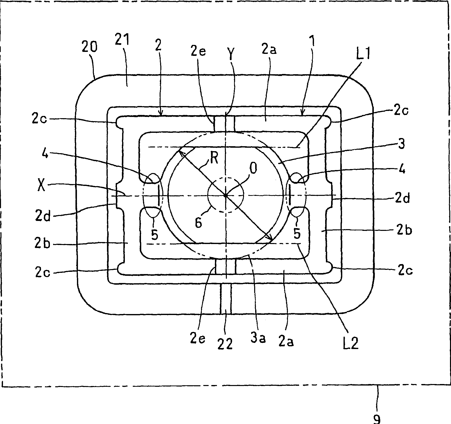
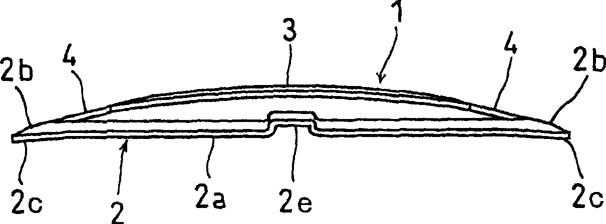
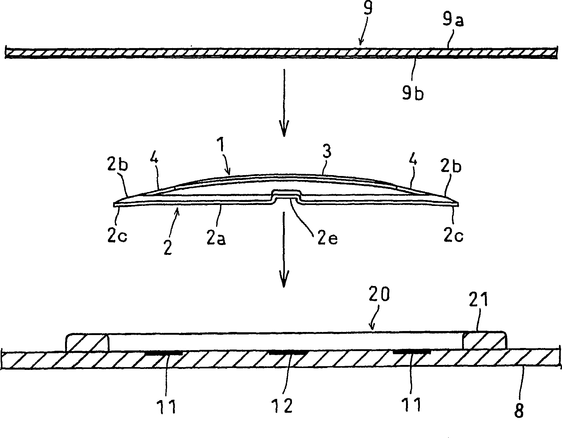
[0030] Embodiments of the present invention will be described below with reference to the drawings. figure 1 It is a plan view showing the push switch of Example 1 of this embodiment, figure 2 It is a side view of the movable contact plate of the push switch of embodiment 1, image 3 It is a side view showing the disassembled state of the push switch of Embodiment 1 before assembly, Figure 4 is a central cross-sectional view showing the assembled state of the push switch of Embodiment 1, Figure 5 It is a central longitudinal sectional view showing the assembled state of the push switch of Embodiment 1, and FIG. 6 is a central cross-sectional view showing the action of the push switch of Embodiment 1.

[0031] The outline of the push switch of the first embodiment will be described. The configuration of this push switch is that first fixed contacts 11, 11 and second fixed contacts 12 are provided on a circuit board 8 such as a printed circuit board (PCB) or a flexible cir...


PUM


Abstract

The invention provided a push-on switch of two stage operation in which a first and a second switches are switched on by pushing operation, in which a movable contact plate is fixed to a circuit board by a pressure-sensitive adhesive tape without deteriorating the operation property of the movable contact plate made of a metallic spring plate. A spacer 20 is arranged at the surroundings of a movable contact plate 1 on a circuit board 8, and by this spacer 20, a continuous or a non-continuous tape pasting surface 21 which is lower than the crown part of a central plate part 3 and higher than a surrounding plate part 2 is formed on the surroundings of the movable contact plate 1, and pasting of the pressure-sensitive adhesive tapes 9, 19 on the surrounding plate part 2 is prevented. The adhesive tape 19 has non-pasting parts 27, 27 at least at a location opposed to the surrounding plate part 2 between the connecting portion to the connecting plate parts 4, 4 of the surrounding plate part 2 of the movable contact plate 1, and thereby, even if the adhesive tape 19 contacts the surrounding plate part 2 at the switching on of the first switch, it is prevented that the adhesive tape 19 is pasted to the surrounding plate part 2.

Description

technical field [0001] The present invention relates to a push switch with two stages of action that is continuously turned on by pressing the first and second switches. Background technique [0002] In the past, such a push switch with two stages of action is known (for example, with reference to the publication No. 7-53234), that is, in the switch housing with the first fixed contact and the second fixed contact inside, a leaf spring made of metal is arranged. Composed of a ring-shaped peripheral plate portion, a central plate portion bent upwards and a movable contact plate connecting them, the connecting plate portion is reversed to a downwardly inclined state by pressing the central plate portion , make contact with the first fixed contact (the first switch is turned on), and then, the center plate part is reversed to a downwardly protruding state, and makes contact with the second fixed contact (the second switch is turned on). [0003] In addition, there is a techniq...

Claims


Application Information

Patent Timeline
IPC IPC(8): H01H13/48H01H13/64H01H13/807
CPCH01H13/807H01H13/64H01H2205/026H01H13/44H01H2225/01H01H13/48H01H2225/018H01H2205/028H01H2213/002
Inventor 浅田信
Owner HOSIDEN CORP
Why Eureka
Try Eureka