

Armature cores for rotating electrical machines
A technology for rotating electrical machines and armature cores, applied in the field of armature cores, can solve problems such as poor productivity, narrow slot openings, and complicated armature coil storage, and achieve the effects of improving productivity and good operating characteristics
- Summary
- Abstract
- Description
- Claims
- Application Information
AI Technical Summary
Problems solved by technology
Method used
Image

Examples
Embodiment approach 1
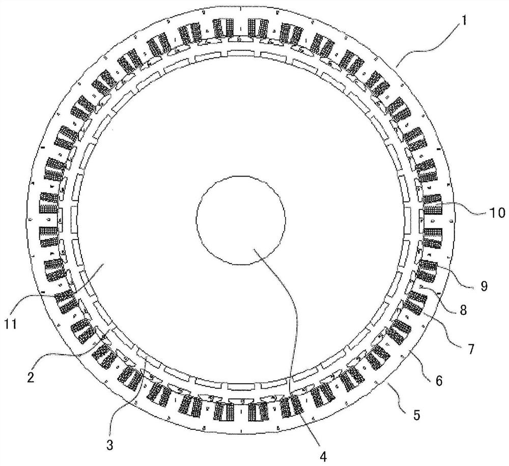
[0032] figure 1 It is a plan view showing the rotating electric machine 1 according to Embodiment 1 of the present invention. exist figure 1 Among them, a rotating electrical machine 1 is configured to include a rotor 2 and an armature 5 . The rotor 2 is fixed to a rotating shaft 4 rotatably supported by a casing (not shown), and is arranged inside the casing. On the other hand, the armature 5 is held by the housing so as to surround the rotor 2 with a certain gap therebetween.
[0033] The rotor 2 includes a rotating shaft 4 and a rotor core inserted into the shaft center and fixed to the rotating shaft 4 . Furthermore, a plurality of magnets 3 are arranged at equal intervals in the circumferential direction on the outer peripheral surface of the rotor core 11 .
[0034] The armature 5 includes an armature core 6 and an armature coil 9 . Armature core 6 has pole teeth 8 . A plurality of magnetic pole teeth 8 protrude radially inward from the inner peripheral wall surfac...
Embodiment approach 2
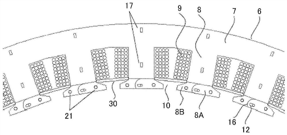
[0055] Figure 8 It is a top view showing rotating electric machine 100 according to Embodiment 2 of the present invention. Figure 9 It is a partially enlarged view of the armature 5 of the rotating electrical machine 100 according to Embodiment 2 of the present invention. The rotating electric machine 100 according to the second embodiment of the present invention has the same configuration as the rotating electric machine 1 according to the first embodiment of the present invention except that it has the fitting portion 40 and the fitting portion 41 .
[0056] Specifically, in the first embodiment described above, only the wedges 30 are used to position and fix the shoe members 80 , 81 . In contrast, in Embodiment 2, it is possible to further use the fitting portion 40 formed by the convex portion of the shoe member 80 and the concave portion of the shoe member 81 , and the concave portion of the magnetic pole tooth 8 and the convex portion of the shoe member 80 . The fit...
Embodiment approach 3
[0068] In Embodiments 1 and 2 of the above invention, the case where both the shoe members 80 and 81 are separate from the magnetic pole teeth 8 has been described. On the other hand, in the third embodiment, a case will be described in which the shoe member 81 and the magnetic pole teeth 8 which do not perform sliding operation are integrally formed.
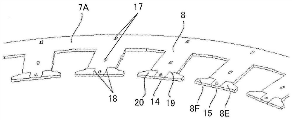
[0069] Figure 12 It is a partially enlarged view of the armature 5 of the rotating electrical machine 100 according to Embodiment 3 of the present invention. Such as Figure 12 As shown, even if the shoe member 81 and the magnetic pole teeth 8 that do not slide are integrally configured, the shoe member 80 can be rotated, and the same effects as those of the first and second embodiments described above can be obtained. At this time, the core pieces 8B, 8D are integrally formed with the core piece 7B, the core piece 8F is formed integrally with the core piece 7A, and the shaft portions 13, 14 are provided on the core pieces 7...
PUM
 Abstract
Description
Claims
Application Information