Thermal overload relay

一种继电器、过载电流的技术,应用在热动型过载继电器领域,能够解决热动型过载继电器动作特性不稳定等问题,达到动作特性稳定的效果

Active Publication Date: 2010-09-29
FUJI ELECTRIC FA COMPONENTS & SYST CO LTD
View PDF5 Cites 1 Cited by
  • Summary
  • Abstract
  • Description
  • Claims
  • Application Information

AI Technical Summary

Problems solved by technology

The operating characteristics of thermal overload relays may become unstable

Method used


Image

  • Thermal overload relay
  • Thermal overload relay
  • Thermal overload relay

Examples


Embodiment Construction

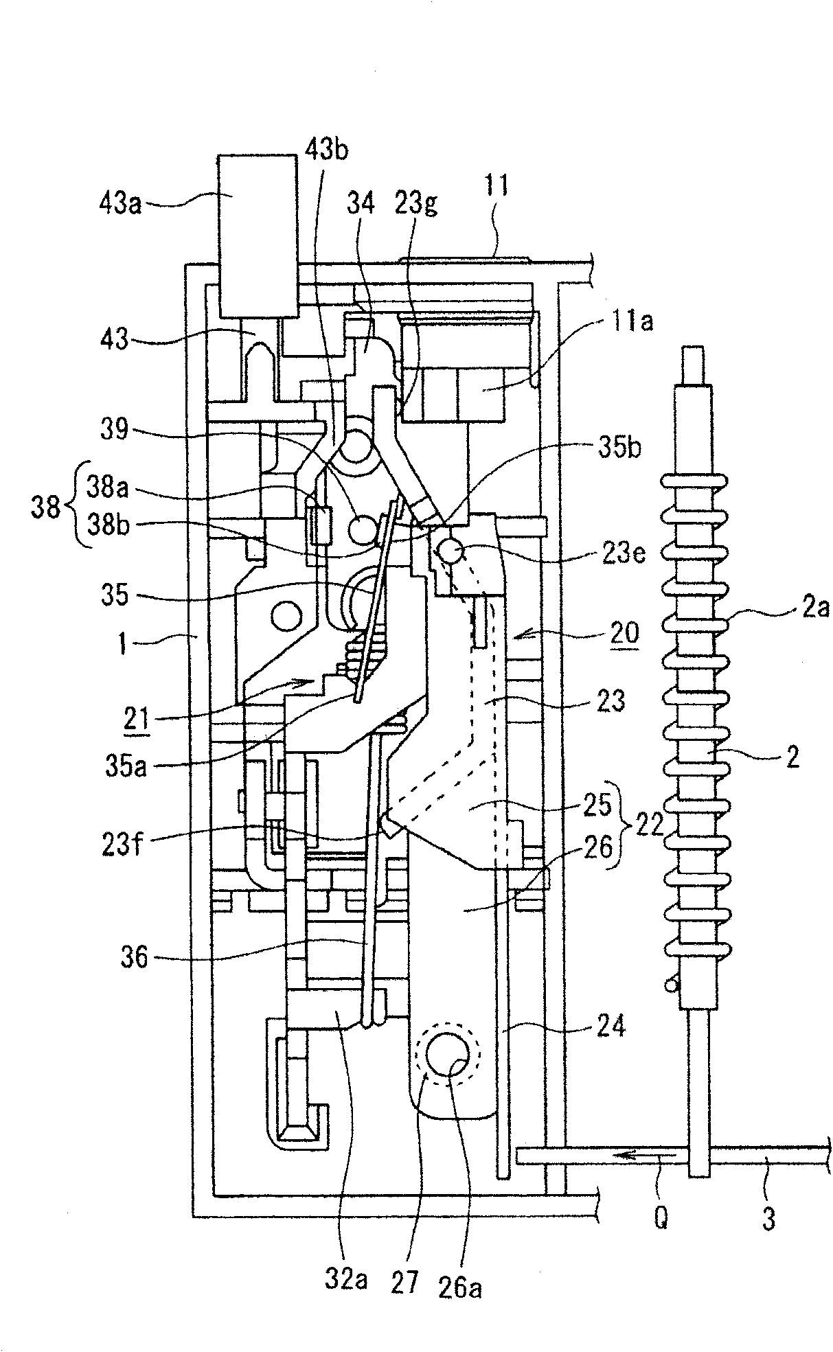
[0086] Hereinafter, the best mode for carrying out the present invention (hereinafter referred to as embodiment) will be described in detail with reference to the drawings. Also, for Figure 8 and Figure 9 Structural components that represent the same structure are marked with the same symbols, and their descriptions are omitted.

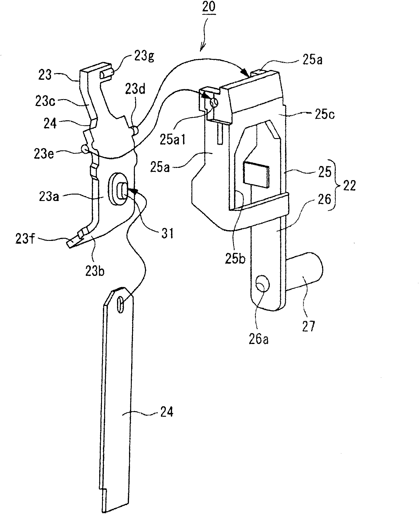
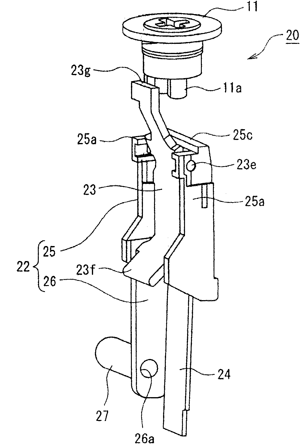
[0087] Figure 1 to Figure 7 Showing one embodiment of the thermal overload relay of the present invention, figure 1 It is a diagram showing the normal state of the main parts of the thermal overload relay, figure 2 It is an exploded diagram of the adjustment mechanism of the thermal overload relay, image 3 is a diagram showing the adjustment mechanism in contact with the adjustment dial, Figure 4 It is a diagram showing the contact inversion mechanism of the thermal overload relay, and Fig. 5(a) is a diagram showing the contact inversion mechanism and the normally open contact (a contact) in the normal state or reset state, and Fig. 5(b) i...


PUM


Abstract

The present invention provides a thermal overload relay which can restrain a bias of reversing acting points of an interface reversing mechanism and perform stable acting characteristics. In the thermal overload relay, the interface reversing mechanism (21) is provided with a movable plate (35) configuring one end (35a) as a support point and the other end (35b) side freely swinging; and a reversing spring (36) stretched between the other side of the movable plate and a spring support (32a) which are positioned opposite a support point. A release lever (23) is integrally formed with a lever supported part (rotating shafts 23d, 23e) rotatably supported by an adjusting link (22); a reversing spring pushing part (23f) formed at an end of one part separating from the lever supported part; a cam contact part (23g) formed at the end of the other part separating from the lever supported part; and a displacement input part (24) clamped with a displaced movement mechanism.

Description

technical field [0001] The present invention relates to a thermal overload relay that switches contacts when overcurrent is detected. Background technique [0002] As a thermal type overload relay which detects and operates the overload current which flows in the main circuit, the apparatus of patent document 1 is known, for example. [0003] refer to Figure 8 and Figure 9 The thermal overload relay of Patent Document 1 will be described. [0004] Such as Figure 8 As shown, in the resin molded insulating case 1, there are housed: inserting each circuit of three phases, a main bimetal 2 wound with a heater 2a; engaging with each free end of these main bimetal 2, The moving mechanism 3 movably supported on the insulating case 1; the reversing mechanism 4 arranged in the insulating case 1 so as to engage with one end of the moving mechanism 3; Opening and closing mechanism 5. [0005] exist Figure 9 It also shows that the reversing mechanism 4 has: a temperature compen...

Claims


Application Information

Patent Timeline
Patent Type & Authority Applications(China)
IPC IPC(8): H01H61/00
CPCH01H83/223
Inventor 古畑幸生森下文浩鸭崎武雄
Owner FUJI ELECTRIC FA COMPONENTS & SYST CO LTD
Why Eureka
Try Eureka