Pull-out faucet

A faucet and pull-out technology, which is applied in the field of pull-out faucets and faucets with pull-out nozzles, can solve the problems of increasing the production cost of faucets and increasing the weight of product shipments, etc.

Inactive Publication Date: 2005-09-28
KOHLER CO
View PDF4 Cites 29 Cited by
  • Summary
  • Abstract
  • Description
  • Claims
  • Application Information

AI Technical Summary

Problems solved by technology

[0006] This will significantly increase the production cost of the

Method used


Image

  • Pull-out faucet
  • Pull-out faucet
  • Pull-out faucet

Examples


Embodiment Construction

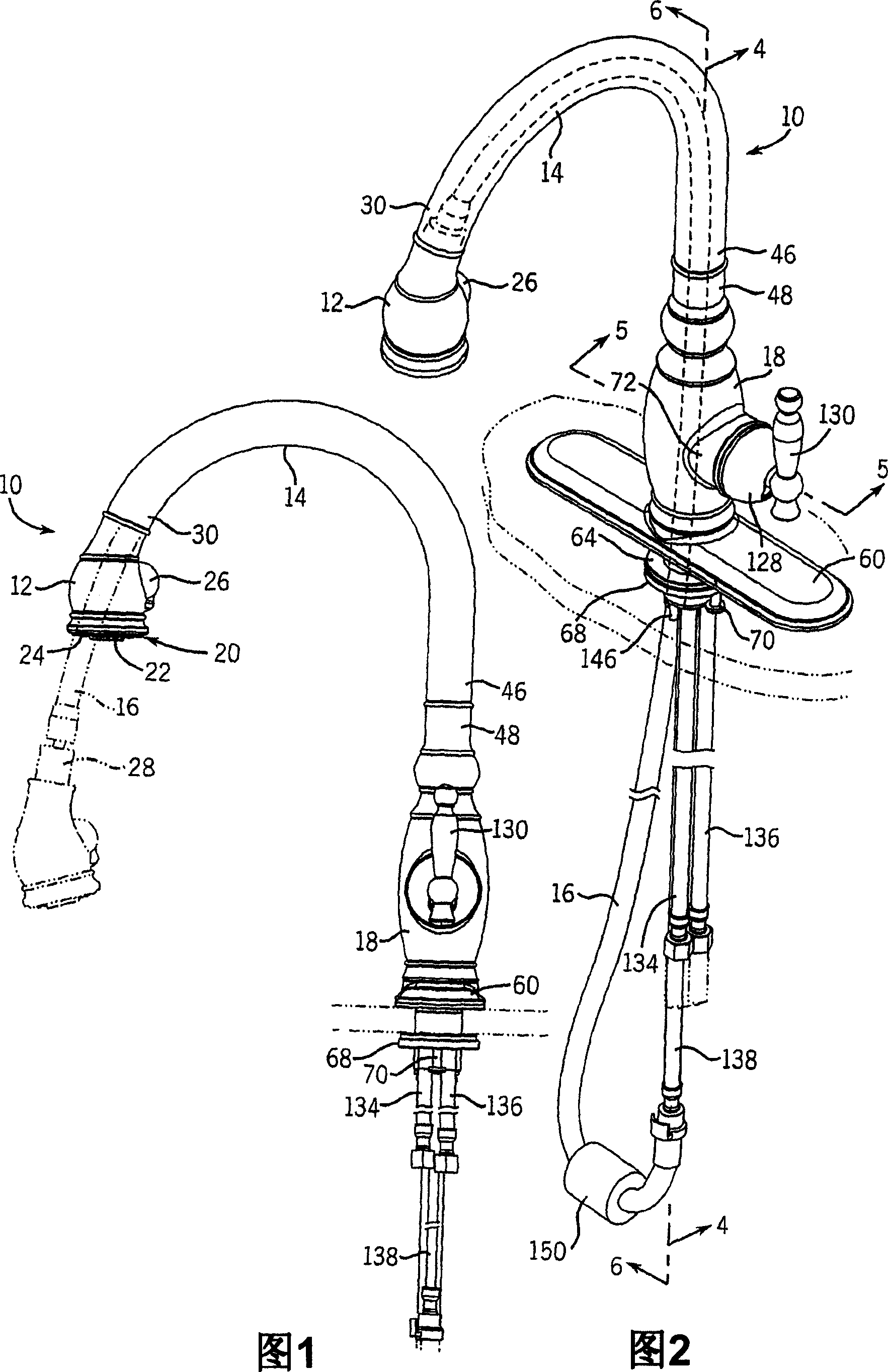
[0028] The main structure of the faucet 10 includes a spout 12 , a spout 14 and a body 18 . Figure 1 shows a preferred version of a pull-out faucet. Figure 2 illustrates that the spout 12 of the tap can be pulled down, in this case first from the (full representation) retracted position down to the (analog representation) extended position. The faucet can thus be used as a conventional faucet with the spray head attached to the spout 14 or detached from the spout for free movement, limited only by the length of the attached spray hose 16 .

[0029] The internal components of the showerhead may be of the type disclosed in US Patent 6,370,713, the entire disclosure of which is incorporated herein by reference, and is commercially available from AMFAG S.p.A. of Castelgoffredo, Italy. Basically, the spray head has a face 20 with a central outlet 22 and a release nozzle ring 24 which provides a shower-like spray when the manual button 26 is depressed to divert the flow of water fr...


PUM


Abstract

A pull-out faucet has a hollow faucet body with open top and bottom ends and a cylindrical (laterally extending) side opening. A hollow, cane-shaped spout mounts to the top end and seats a spray head at one end. A separate valve block mounts in the housing through the side opening and connects to a mixing valve cartridge lying adjacent thereto on a lateral side. Water supply hoses snap into inlet passages of the valve. One end of a counterweighted spray hose assembly snaps into an outlet passage of the valve block and the other end connects to the spray head. The spray head can be extended from the spout and then retracted. A method of assembling the hoses and valve assembly into the hollow faucet body through the side opening is also disclosed.

Description

Background technique [0001] The invention relates to a water faucet, in particular to a water faucet with a pull-out spray head. [0002] A conventional faucet has a faucet body, one or more flow control / mixing valves, one or more control handles, and a spout. The spout acts as a drain for the flow of water passing through the valve, in which case the outflow is either fixed at a single point of activation, or limited to a preset horizontal arc in the case of a rotating spout. [0003] Therefore, faucets are traditionally equipped with separate independent manual spray heads to provide users with more flexibility in terms of the direction and point of activation of the outflow, especially to facilitate downward spraying of vessels. This spray head has a flexible tube that is attached to the spray head and allows the spray head to be pulled from the holder and moved as desired. However, these faucets require additional space on the reverse top for installation of the spray he...

Claims


Application Information

Patent Timeline
IPC IPC(8): E03C1/04F16K11/078
CPCY10T137/86815E03C1/04E03C2001/0415E03C1/042
Inventor J·C·埃舍
Owner KOHLER CO
Why Eureka
Try Eureka