Method of linking two knit fabrics

A technology of knitting and parts, which is used in the field of connecting two knitted parts, can solve the problems of time-consuming and increase the cost of textiles, and achieve the effect of saving time

Inactive Publication Date: 2005-10-12
H STOLL GMBH & CO KG
View PDF0 Cites 5 Cited by
  • Summary
  • Abstract
  • Description
  • Claims
  • Application Information

AI Technical Summary

Problems solved by technology

[0003] Hitherto the stitching methods used to join knitted parts were rather time-consuming and thus increased the cost of manufacturing the entire textile

Method used


Image

  • Method of linking two knit fabrics
  • Method of linking two knit fabrics
  • Method of linking two knit fabrics

Examples


Embodiment Construction

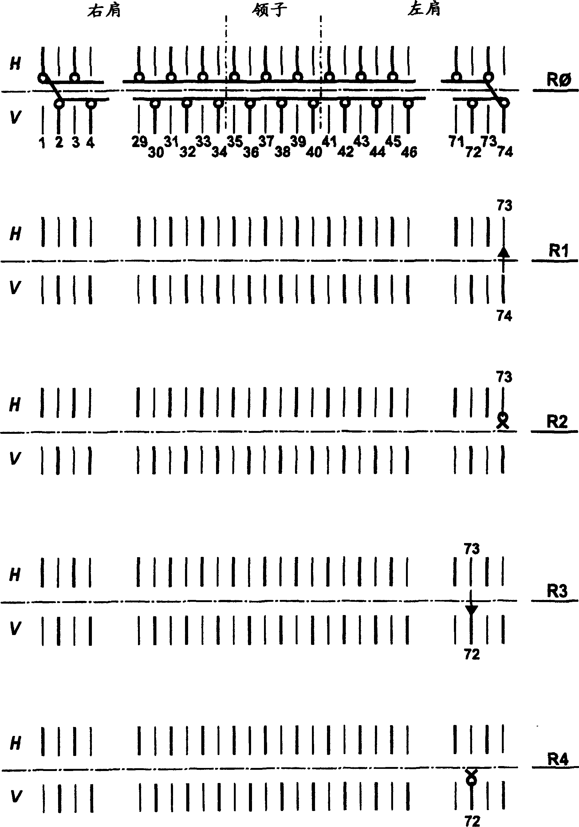
[0026] figure 1 Taking the knitted round neck sweater as an example, it shows a connection technique in the prior art by means of a common sewing method. The rear needle bed H is the second needle bed and can perform traverse movement. Row R0 shows the last normally formed knitting row of the knitted crew neck sweater. A portion of the mesh forms the right shoulder area, a portion of the mesh forms the collar and the remaining portion of the mesh forms the left shoulder area. A needle bed V, H has a mesh on every other needle, wherein the knitting needles with the mesh on one needle bed are opposite to the empty needles on the other needle bed.

[0027] In row R1, the rear needle bed moves one stitch to the right. For this purpose, the edge mesh 74 on the front of the knitwear is suspended from the edge mesh 73 on the back of the knitwear. Then in row R2, the two meshes suspended from the needles 73 are knitted, thereby forming a stitching mesh connecting the two meshes to...


PUM


Abstract

The invention relates a method for connecting two knitting parts by suture techniques on a flat knitting machine with at least two relative needle bars, according to the method the edge coils of the needle bars are hung over a suture coil to weave so that the needle bars can be connected mutually when a new suture coil is formed.

Description

technical field [0001] The invention relates to a method for joining two knitted parts on a flat knitting machine having at least two opposing needle beds. Background technique [0002] Such a connection purpose of two knitted parts occurs, for example, in the shoulder area of ​​a T-shirt. However, it is also required to connect knitted parts on other clothing parts and industrial knitwear. [0003] The stitching methods hitherto used to join knitted parts are rather time-consuming and thus increase the costs of manufacturing the entire textile. Contents of the invention [0004] The object of the present invention is to provide a method for joining two knitted parts on top which requires only a short machine operating time but which produces a high-quality joint. [0005] This object is achieved with a method of the type mentioned at the beginning, which is characterized according to the invention by the following steps: [0006] a) setting the mesh of the first knitte...

Claims


Application Information

Patent Timeline
Patent Type & Authority Applications(China)
IPC IPC(8): D04B1/22D04D1/00D04D7/00
CPCD04B1/22
Inventor H·施密德特T·诺嫩马赫尔F·科卢拉
Owner H STOLL GMBH & CO KG
Why Eureka
Try Eureka