Self contained lubricant dispenser

A technology for dispensing devices, lubricants, applied in the directions of dispensing devices, special dispensing devices, liquid dispensing, conveying or transferring devices, etc., can solve problems such as less choice

Inactive Publication Date: 2005-10-12
GRACO INC
View PDF0 Cites 15 Cited by
  • Summary
  • Abstract
  • Description
  • Claims
  • Application Information

AI Technical Summary

Problems solved by technology

[0002] While large vehicle maintenance and servicing facilities have a variety of options for automated metered dispensing of fluids, smaller facilities that perform relatively few daily oil changes (eg 5) have fewer options in this regard

Method used


Image

  • Self contained lubricant dispenser
  • Self contained lubricant dispenser
  • Self contained lubricant dispenser

Examples


Embodiment Construction

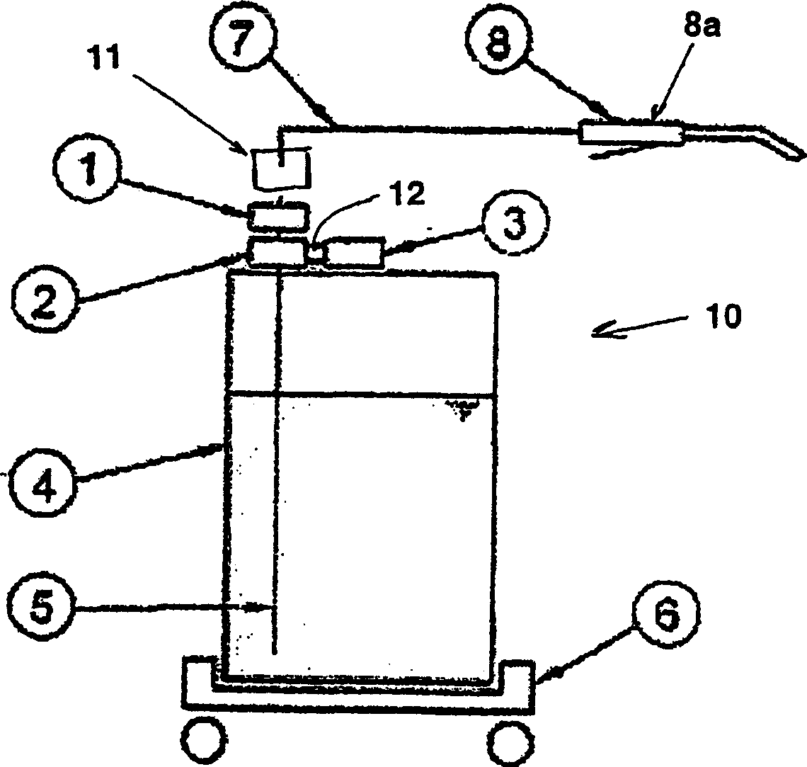
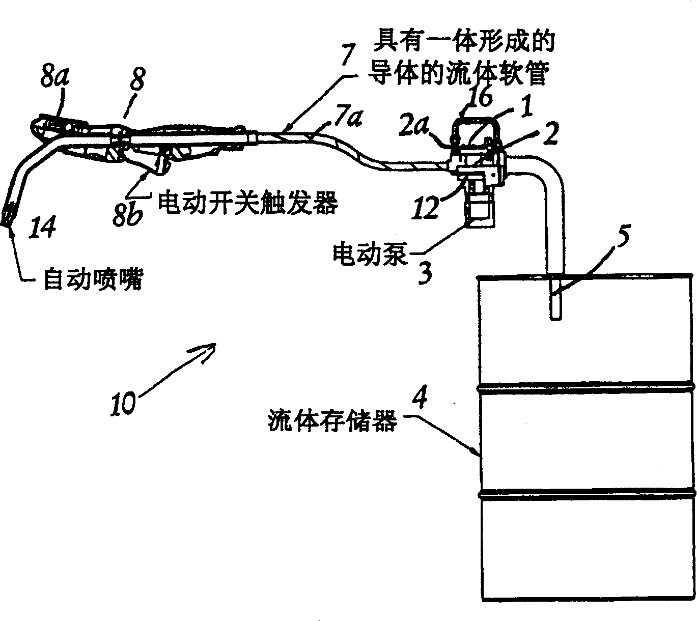
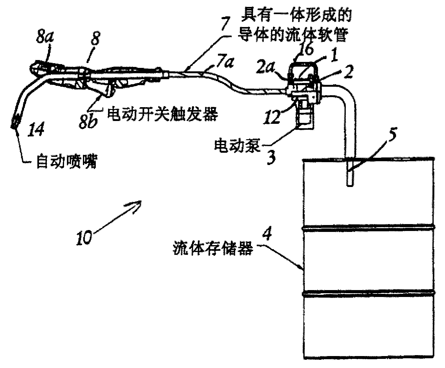
[0008] The invention, generally designated 10, comprises a flow meter 1 and a pump 2 associated therewith. In the preferred embodiment, these two elements are combined, wherein the pump 2 is a gerotor pump type pump, and by placing a Hall effect sensor 2a in the gerotor pump housing to calculate the The pulse generated by the gear teeth displacement of the internal gear oil pump forms the flow meter 1.

[0009] The DC motor 3 drives the pump 2 through a gearbox 12 in order to reduce the rotational speed level. In the preferred embodiment, the motor 3 runs at 20,000 RPM and decelerates to about 600 RPM to produce a flow rate of about 1.5 gallons per minute. The dispensing device 10 is designed to fit over a large volume fluid container 4 and has a suction tube 5 depending downwardly into the container 4 . A portable base 6 can also be provided.

[0010] The dispensing hose 7 leads to a dispensing valve 8, which has a display device 8a indicating the dispensing amount. Dispe...


PUM


Abstract

An integrated design for dispensing lubricants and similar fluids from bulk containers incorporates a dispense valve (8), a meter (1), a hose (7), a DC powered electric pump (2), power cord (18) and adjustable fluid suction tube (5), all packaged in one portable unit. The unit is capable of dispensing fluids such as standard SAE grade automotive motor oils, automatic transmission fluid, gear lube, hydraulic oil and engine coolant (antifreeze). The pump motor will shut down at completion of dispense; and emergency shut-off to be provided.

Description

technical field [0001] This application claims the benefit of US Application No. US 60 / 412,530, filed September 20,2002. Background technique [0002] While large vehicle maintenance and servicing facilities have several options for automatic metered dispensing of fluids, smaller facilities that perform relatively few daily oil changes (eg, 5) have few options in this regard. In these applications, the lubricant can be dispensed by: (1) decanting from a quart / liter container; (2) hand pumping from a bulk container; or (3) in a pail or other container Fill with the desired amount of lubricant and pour from this container into the vehicle. Contents of the invention [0003] It is an object of the present invention to provide a portable integrated oil dispensing unit primarily for use in auto repair shops and low volume service stations where fluid is dispensed in small quantities and infrequently. [0004] For this purpose, the all-in-one design includes a dispensing valve...

Claims


Application Information

Patent Timeline
Patent Type & Authority Applications(China)
IPC IPC(8): B65DB65D88/54B67D7/04B67D7/66B67D7/84F16N9/00G01F11/06
CPCB67D7/845B67D7/66B67D7/04F16N9/00
Inventor 克里斯蒂安·D·科克布莱德·威尔逊马克·金托马斯·尼斯
Owner GRACO INC
Why Eureka
Try Eureka