Optical tomography of small moving objects using time delay and integration imaging

An object and optical technology used in the field of optical tomography imaging systems

Inactive Publication Date: 2005-10-19
VISIONGATE
View PDF4 Cites 7 Cited by
  • Summary
  • Abstract
  • Description
  • Claims
  • Application Information

AI Technical Summary

Problems solved by technology

object of interest is centered

Method used


Image

  • Optical tomography of small moving objects using time delay and integration imaging
  • Optical tomography of small moving objects using time delay and integration imaging
  • Optical tomography of small moving objects using time delay and integration imaging

Examples


Embodiment Construction

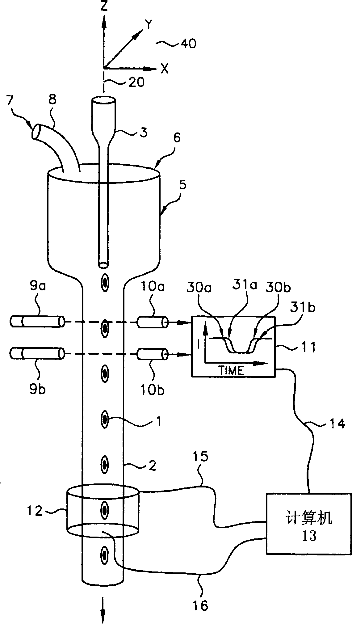
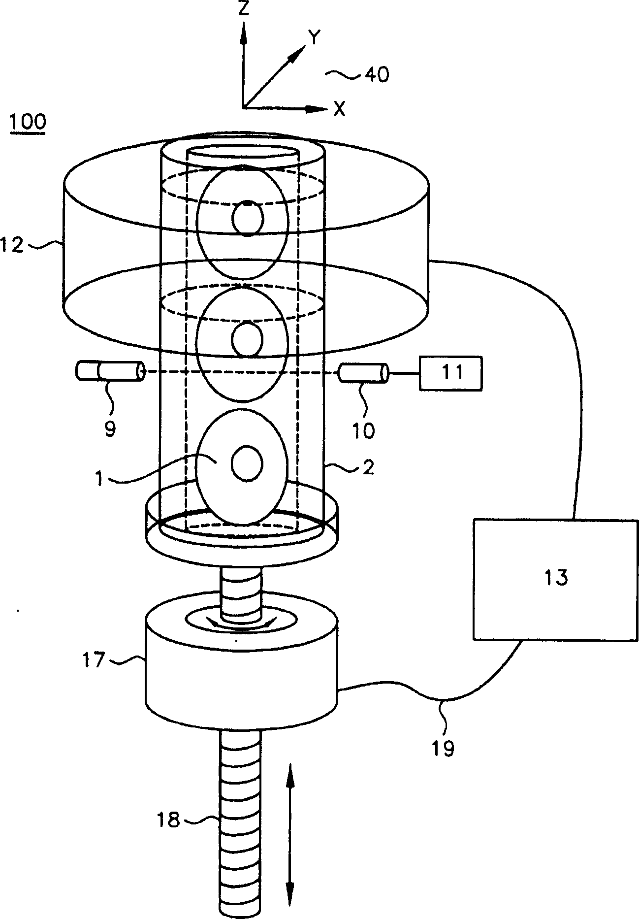
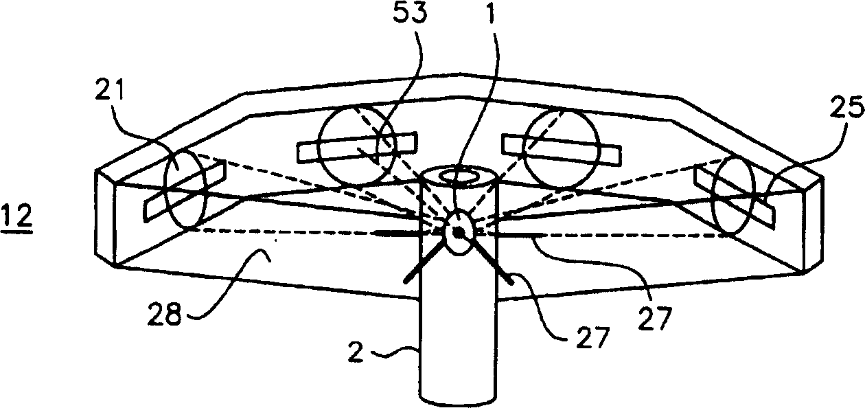
[0019] The present invention is described herein with respect to specific examples of biological cells, however, it should be understood that these examples are for the purpose of explaining the principles of the invention and not limiting the invention. In one example, constructing a three-dimensional distribution of optical density in the space under the microscope enables quantification and localization of structures, molecules or molecular probes of interest. By using labeled molecular probes, it is possible to determine the amount of probes attached to a particular structure in a microscopic object. For purposes of illustration, an object such as a biological cell can be labeled with at least one spot or labeled molecular probe, the measurement of the number and location of which can yield important information about the disease state of the cell. Various cancers are included, such as, but not limited to, lung cancer, breast cancer, prostate cancer, cervical cancer, and o...


PUM


Abstract

Three dimensional reconstruction of an object of interest moving at a constant velocity. The object of interest is centered. The object of interest is imaged with optical point sources located at multiple projection angles around the object of interest, in cooperation with opposing time delay and integration (TDI) image sensors located at a distance from the objects of interest such that there is no focal plane within the objects of interest during imaging. Each of the TDI sensors has a line transfer rate synchronized to the constant velocity of the objects of interest.

Description

[0001] related application [0002] This application is pending U.S. Application Serial No. 09 / 927,151 filed August 10, 2001 by Alan C. Nelson, now Serial No. 6,522,775 and published July 8, 2003, entitled "Using Optical Tomography Apparatus and Method for Imaging Small Objects in a FlowStream Using Optical Tomography (Apparatus and Method for Imaging Small Objects in a FlowStream Using Optical Tomography). technical field [0003] The present invention relates generally to optical tomography imaging systems, and more particularly to optical tomography for imaging objects using optical tomography and time delay and integration. Background technique [0004] US Application 10 / 126,026, entitled "Variable-Motion Optical Tomography of Small Objects," filed April 19, 2002 by Alan Nelson is hereby incorporated by reference. In the Nelson application, the projected image of the video is captured digitally by a conventional CCD or CMOS image detector. When imaging moving objects, ...

Claims


Application Information

Patent Timeline
Patent Type & Authority Applications(China)
IPC IPC(8): G01N15/14G01N21/05G01N21/17G01N21/47G01N21/64G01N21/78G01N23/04G01N33/543G01N33/554G01N33/60G06T1/00G06T3/00G06T11/00
CPCG01N23/046G06T11/006G01N21/4795G01N15/147G01N21/05G01N2223/419
Inventor 周志伟A·C·纳尔逊
Owner VISIONGATE
Why Eureka
Try Eureka