In site synthetic measuring method and apparatus for conductivity of variable density fibre aggregate

A fiber aggregate and comprehensive measurement technology, which is applied in the direction of measuring device, specific gravity measurement, measuring distance, etc., can solve the problem that there is no combined in-situ measurement method and device, and achieve a high degree of automation, low interference, and strong comprehensiveness Effect

Inactive Publication Date: 2005-10-26
DONGHUA UNIV
View PDF2 Cites 15 Cited by
  • Summary
  • Abstract
  • Description
  • Claims
  • Application Information

AI Technical Summary

Problems solved by technology

The reason is very simple. At present, there is no combined in-situ measurement method and device to achieve this requirement.

Method used


Image

  • In site synthetic measuring method and apparatus for conductivity of variable density fibre aggregate
  • In site synthetic measuring method and apparatus for conductivity of variable density fibre aggregate
  • In site synthetic measuring method and apparatus for conductivity of variable density fibre aggregate

Examples


Embodiment 1

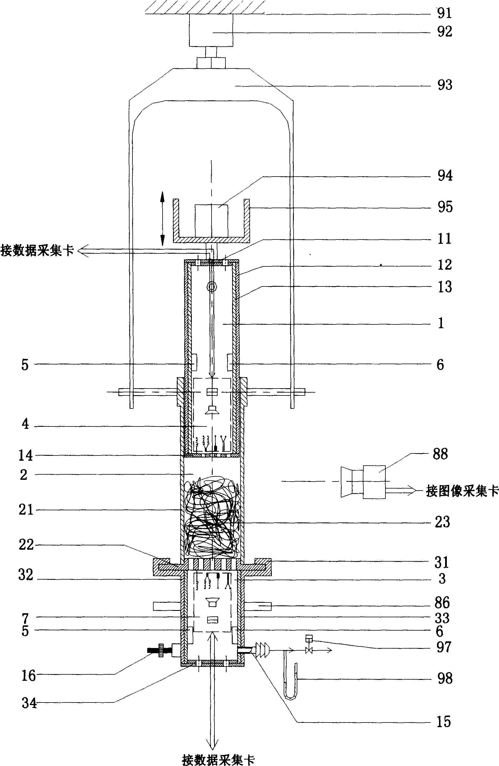
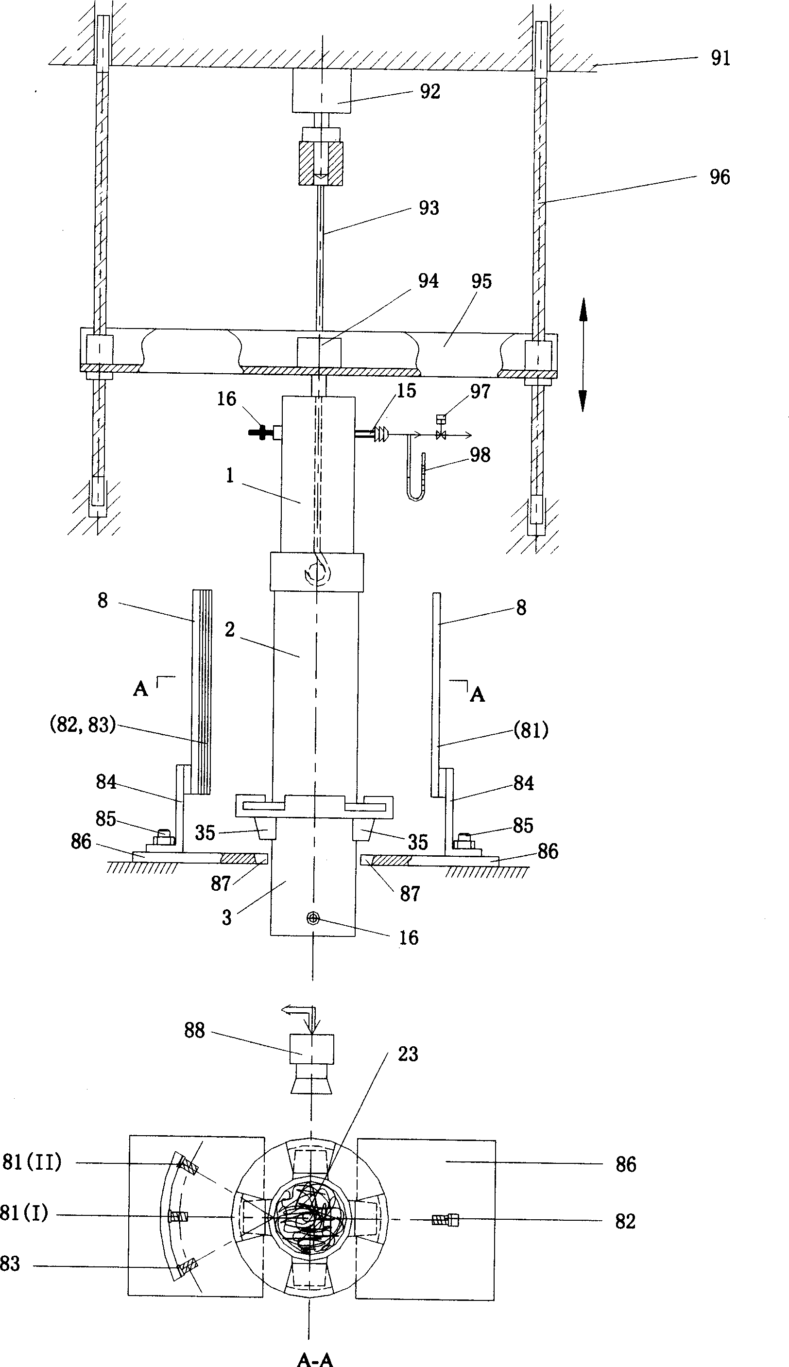
[0050] Using the in-situ comprehensive measuring device of the present invention, according to the above-mentioned actual measurement operation description, take 2g of wool fiber samples, fill them in the fiber plug tube 2 randomly and evenly in a natural relaxation state, and perform a compression mode extrusion. Fully open the air hole window 11 on the upper end of the push tube measuring chamber 1 before extrusion to ensure that the air pressure at one end of the fiber plug 23 is normal pressure; the air hole window 34 at the bottom of the lower measuring chamber 3 is completely closed, and start pumping to make the lower measuring chamber 3 produce a negative pressure. Press to form the air pressure difference ΔP at both ends of the fiber plug. Push cylinder to measure air pressure P in chamber 1 1 Measured by the air pressure sensor 46 in the upper measuring unit 4; the air pressure P of the lower measuring chamber 2 Measured by the air pressure sensor 76 in the lower me...

Embodiment 2

[0052] According to the sample and test conditions described in Example 1, while the extrusion test is applied, an electric field is applied to the wool fiber plug, that is, the electrodes 41 in the upper measurement unit 4 and the electrodes 71 in the lower measurement unit respectively apply an electric field to the fiber plug. Apply a voltage to the metal plates 14 and 22 of the end porous structure, and measure the current flowing through the fiber plug at this time to obtain the resistance R of the fiber plug. The fiber plug is constantly squeezed, and the resistance changes synchronously. As a result, the resistance R-fiber plug density ρ curve is shown in the attached Figure 7 Shown, is a clear resistance attenuation process.

Embodiment 3

[0054] According to the sample and test conditions described in Example 1, while the extrusion test is applied, the wool fiber plug is subjected to acoustic action, that is, in the lower measurement chamber 3, the sound emitter 74 in the lower measurement unit 7 outputs a fixed frequency ( 4000Hz audio), the sound pressure is 82dB. The sound pressure intensity I measured by the acoustic sensor 75 in the lower measuring chamber 3 1 It is 79.4dB when it is not squeezed; the sound pressure I 2 , the percentage of sound pressure intensity at both ends of the fiber plug is α t = I 2 / I 1 ×100%. The measured sound intensity I-fiber plug density ρ curve and sound intensity percentage α t — fiber plug density ρ curve, respectively as Figure 8 and Figure 9 shown.


PUM


Abstract

This invention is variable density fibre complex conductivity in situ synthesis measuring method and device. Apply force on fibre plug, change the density of the fibre plug, and apply air, voice, electricity, heat, humidity effects. And use force, air, voice, electricity, heat, humidity sensor to measure the change of the physical appearance density and distribution. The device can improve the structure and isolation of the push silo, fiber plug and measure chamber, and add measure units , related drive and control circuit, modular used for data collection and treatment and interface control, in push silo and measure chamber. This device can actualize the conduction, isolation of variable density fibre complex's in situ synthesis measurement. This measurement has high accuracy and little disturbance. It can be widely used in many kinds of measurement.

Description

Technical field: [0001] The invention relates to precise and multifunctional measurement technology, and belongs to an in-situ comprehensive measurement method and device for the conductivity of fiber aggregates. Background technique: [0002] Fiber aggregates are mostly used for filling flakes, wearing protection, flexible insulation and other materials or structures. However, in practical applications, first, materials with different filling densities are required to achieve good insulation and protection, or conduction and filtration; The failure of the original design performance; third, the density distribution in the compression of the fiber aggregate will change, and it is not uniform, the expression of theory and practice is average or non-original in situ, and cannot correctly reflect the change of its conductivity . Therefore, when the density of the fiber aggregate changes or the density is uniform, its influence on the conductivity has become a difficult point ...

Claims


Application Information

Patent Timeline
Patent Type & Authority Applications(China)
IPC IPC(8): G01N35/00
Inventor 于伟东刘茜
Owner DONGHUA UNIV
Why Eureka
Try Eureka